Table of Contents
Advertisement
Quick Links
Advertisement
Table of Contents

Subscribe to Our Youtube Channel
Summary of Contents for Insportline IN 14168
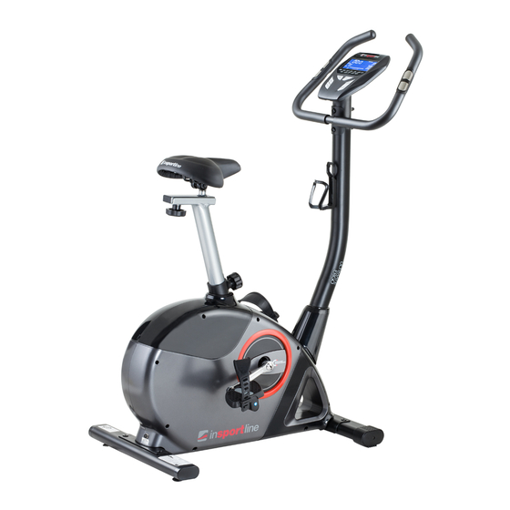
- Page 1 USER MANUAL – EN IN 14168 Exercise Bike inSPORTline Salenas...
-
Page 2: Table Of Contents
CONTENTS SAFETY INSTRUCTIONS ........................3 PARAMETERS ............................3 ASSEMBLY ............................. 4 Package contents ..........................5 Assembly steps ............................ 6 CONTROL PANEL ..........................12 Display functions ..........................12 Key functions............................13 Operations............................13 CORRECT WORKOUT POSITION ....................... 15 EXPLODED DRAWING ......................... 16 PARTS LIST ............................ -
Page 3: Safety Instructions
SAFETY INSTRUCTIONS Read carefully the entire manual before using this product. Retain the manual for future reference. • Exercise of a strenuous nature, as is customarily done on this equipment, should not be undertaken without first consulting a physician. No specific health claims can be made or implied as they relate to the equipment. -
Page 4: Assembly
ASSEMBLY... -
Page 5: Package Contents
Package contents Tools: Washer Φ12*Φ19*1T Allen bolt M8*16L (4) Acorn nut for M8 bolt Curved washer Φ8*Φ19*2T (2) M-3 (2) M-2 (4) M-5 Carriage bolt M8*75L (2) M-1 Allen Key (1) Box spanner (1) Screwdriver (1) Parts: Main frame Handlebars Handlebar post Saddle Front stabilizer... -
Page 6: Assembly Steps
Seat post Bottle holder D-30 Control panel Pedals Tools Adapter Assembly steps STEP 1 1. Attach the front stabilizer (I) to the main frame (D) using two screws & washers (M-4, M-5). 2. Attach the rear stabilizer (J) to the main frame (D) using two screws & washers (M-4, M-5). STEP 2 Screw the two pedals (D-30L + D-30R) onto the cranks (D-13L, D-14R) with a screw driver. - Page 7 NOTE: Screw the left pedal’s spindle counter-clockwise and the right pedal’s spindle clockwise. Use a wrench (or a screwdriver) to screw the two spindles completely. STEP 3 1. Affix the seat (O) onto the seat slider. The slider can be adjusted to different angles. Tighten the two nuts under the seat using a screwdriver.
- Page 8 NOTE: Adjust the height of the seat so that the holes on the knob and the seat post align. If you loosen the knob and move the seat post up and down, the knob should lock into a hole in the seat post.
- Page 9 STEP 4 1. Connect the upper and lower sensor wire (C-1, D-23). 2. Insert the handlebar post (C-3) into the main frame with screws (D-24) and semi-circular washers (D-25) using an Allen wrench.
- Page 10 STEP 5 1. Pass the hand-pulse wire (B-3) through the hole. 2. Affix the handlebar (B) onto the handlebar post (C-3) using screws (M-1), nuts (M-2) and semi washers (M-3).
- Page 11 STEP 6 Plug the wire (B-3 & C-1) and attach the computer (A) with 4 screws (A-1) using a box wrench.
-
Page 12: Control Panel
STEP 7 1. Attach the water bottle (E) cage using screws (C-2). 2. Plug the adapter (N) into a socket as pictured below. CONTROL PANEL Display functions ITEM DESCRIPTION TIME Displays workout time during exercise. Range: 0:00 ~ 99:59 min SPEED Displays workout speed during exercise. -
Page 13: Key Functions
CALORIES Displays burnt calories during exercise. Range: 0 ~ 999 cal PULSE Displays beats per minute during exercise An alarm will notify you, you your heart rate overreaches the target frequency. Displays rotations per minute. Range: 0 ~ 999 rpm WATTS Displays workout power consumption. - Page 14 MANUAL MODE 1. Press START in the main menu to start a workout in the manual mode. 2. Press UP or DOWN to select a workout program, choose “Manual”, and press MODE to enter. 3. Press UP or DOWN to preset TIME, DISTANCE, CALORIES and PULSE and press MODE to confirm.
-
Page 15: Correct Workout Position
3. Press UP or DOWN to preset the workout time. 4. Press the START/STOP button to start or stop the workout. Press RESET to return to main menu. WATT MODE 1. Press UP or DOWN to select a workout program, choose “WATT” and press MODE to enter. 2. -
Page 16: Exploded Drawing
EXPLODED DRAWING... -
Page 17: Parts List
PARTS LIST Description Description Console Pulley Screw M5*P0.8*10L Bearing 6900RS Handlebar set Bearing 6003RS Foam grip Bearing 6203 Hand pulse Bearing 6300RS Hand pulse wire Flat washer Screw M4*20L F-10 Star washer End cap F-11 Bushing of flywheel Handlebar F-12 Bushing of flywheel Handlebar post set F-13... -
Page 18: Terms And Conditions Of Warranty, Warranty Claims
D-22 Servo motor set Seat post D-23 Motor wire Seat slider set D-24 Screw M8*P1.25*20L Fixing screw bracket D-25 Semi washer Knob of seat D-26 Axle Flat washer Hexagonal screw D-27 End cap M8*P1.25*12L D-28 Pulley Seat slider D-29 Bushing Hardware kit set D-30 Pedal set... - Page 19 By the Warranty for Goods Quality, the Seller guarantees that the delivered Goods shall be, for a certain period of time, suitable for regular or contracted use, and that the Goods shall maintain its regular or contracted features. The Warranty does not cover defects resulting from (if applicable): •...
- Page 20 E-mail: eshop@insportline.cz reklamace@insportline.cz servis@insportline.cz Web: www.insportline.cz INSPORTLINE s.r.o. Headquarters, Warranty & Service centre: Elektricna 6471, 911 01 Trencin, Slovakia CRN: 36311723 VAT ID: SK2020177082 Phone: +421(0)326 526 701 E-mail: objednavky@insportline.sk reklamacie@insportline.sk servis@insportline.sk Web: www.insportline.sk Date of Sale: Stamp and Signature of Seller:...


Need help?
Do you have a question about the IN 14168 and is the answer not in the manual?
Questions and answers