DEVI DEVIreg 610 Installation Manual
Hide thumbs
Also See for DEVIreg 610:
- Installation and use instructions manual (10 pages) ,
- Installation instruction (28 pages)
Table of Contents
Advertisement
Quick Links
Advertisement
Table of Contents

Related Manuals for DEVI DEVIreg 610


Summary of Contents for DEVI DEVIreg 610
- Page 1 Installation Guide DEVIreg™ 610 Electronic Thermostat www.DEVI.com...
-
Page 3: Table Of Contents
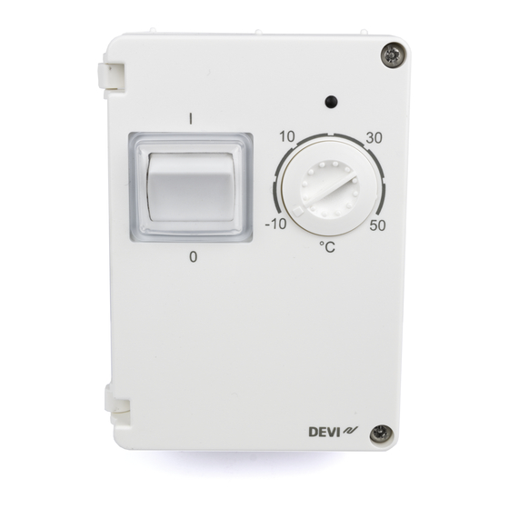
The thermostat has a button for adjusting the temperature setting with a scale from -10° to +50°C, and an LED indica- tor that shows standby periods (green light) and heating periods (red light). More information on this product can also be found at: devireg.devi.com Installation Guide... -
Page 4: Technical Specifications
DEVIreg™ 610 Technical Specifications Operation voltage 220-240V~, 50Hz Standby power consumption Max. 0.93W Relay: Resistive load Max 10A / 2300W @ 230V Inductive load cos φ= 0.3 max 1A Sensing units NTC 15kOhm at 25°C Sensing values: 0°C 42kOhm 25°C 15kOhm 50°C 6kOhm... -
Page 5: Safety Instructions
DEVIreg™ 610 Dimensions 100 x 69.5 x 45mm Weight 165g The product complies with the EN/IEC Standard "Automatic electrical controls for household and similar use": ▪ EN/IEC 60730-1 (general) ▪ EN/IEC 60730-2-9 (thermostat) Safety Instructions Make sure the mains supply to the thermostat is turned off before installation. -
Page 6: Mounting Instructions
DEVIreg™ 610 Mounting Instructions Please observe the following placement guidelines: ▪ The thermostat can be placed both indoors and out- doors. ▪ Place the thermostat on a wall, pole, steel/wooden plate or pipe. In wet rooms, place the thermostat according to local regulation on IP classes. - Page 7 DEVIreg™ 610 Follow the steps below to mount the thermostat: 1. Open the thermostat: -1 0 -1 0 ▪ Set adjustment button to minimum temperature. ▪ Loosen the 2 screws and open the front cover. Installation Guide...
- Page 8 DEVIreg™ 610 2. Fasten the thermostat: ▪ Drive the screws through the holes in the bottom corners of the thermostat. ▪ Seal the holes with the enclosed screw stopper to maintain the density. Installation Guide...
- Page 9 DEVIreg™ 610 3. Connect the thermostat according to the connection diagram. IP44 -10T50 D610 N NO NC Mains Max.Load 220-240V~ 10 (1) A ▪ Heating: (L-main, N-main, L-load, NO (normally open) - load). ▪ Cooling: (L-main, N-main, L-load, NC (normally closed) - load).
- Page 10 DEVIreg™ 610 6. Install sensor using the supplied sensor cable - spec. NTC 15 kΩ @ 25°C. ▪ Press out the blanket located at the bottom of the thermostat and insert the seal nipple. ▪ Connect sensor to terminals 6+7. The sensor cable can be extended up to 50 m with 1.5 mm²...
-
Page 11: Warranty
DEVIreg™ 610 Warranty Y E A R Disposal Instruction Installation Guide... - Page 12 DEVIreg™ 610 Installation Guide...
- Page 13 DEVIreg™ 610 Installation Guide...
- Page 14 DEVIreg™ 610 Installation Guide...
- Page 15 This also applies to products already on order provided that such alterations can be made without subsequential changes being necessary in specifications already agreed. All trademarks in this material are property of the respective companies. DEVI and the DEVI logo- type are trademarks of Danfoss A/S.
Need help?
Do you have a question about the DEVIreg 610 and is the answer not in the manual?
Questions and answers