
Related Manuals for DEVI DEVIreg Smart


Summary of Contents for DEVI DEVIreg Smart
- Page 1 Installation Guide DEVIreg™ Smart Intelligent Electronic Timer Thermostat with Wi-Fi connectivity and App control www.DEVI.com...
-
Page 2: Table Of Contents
DEVIreg™ Smart Table of Contents Introduction � � � � � � � � � � � � � � � � � � � 2 Technical Specifications � � � � � � � � � � � � 4 Safety Instructions �... - Page 3 DEVIreg™ Smart • A touchscreen display with light. • An easy-to-follow menu-driven programming and operation. • An installation wizard with room/floor type-specific setup (requires an app). • Support for multiple frame systems. • Compatible with several 3rd party NTC sensors. •...
-
Page 4: Technical Specifications
DEVIreg™ Smart More information on this product can also be found at: devismart�com Technical Specifications Operation voltage 220-240 V~, 50/60 Hz Standby power consumption Max. 0,40 W Relay: Resistive load Max. 16 A / 3680 W @ 230 V Inductive load Max. - Page 5 DEVIreg™ Smart Frost protection 5°C to +9°C (default 5°C) temperature Temperature range Room temperature: 5-35°C. Floor temperature: 5-45°C. Max. floor: 20-35°C (if unrecov- erable seal is broken then up to 45°C). Min. floor: 10-35°C, only with combination of room and floor sensor. Sensor failure monitoring The thermostat has a built-in monitoring circuit, which will...
-
Page 6: Safety Instructions
DEVIreg™ Smart Protection class Class II - Dimensions 85 x 85 x 20-24 mm (in-wall depth: 22 mm) Weight 127 g Electrical safety and Electro-Magnetic Compatibility for this product is covered by the compliance with the EN/IEC Standard “Automatic electrical controls for household and similar use”: •... - Page 7 DEVIreg™ Smart Please also note the following: • The installation of the thermostat must be done by an authorized and qualified installer according to local regulations. • The thermostat must be connected to a power supply via an all-pole disconnection switch. •...
-
Page 8: Mounting Instructions
DEVIreg™ Smart Mounting Instructions Please observe the following placement guidelines: Place the thermostat at a suitable height on the wall (typically 80-170 cm.). The thermostat should not be placed in wet rooms. Thermostat must be placed outside zone 3. Place it in an adjacent room and use floor sensor only. - Page 9 DEVIreg™ Smart Note: A floor sensor is recommended in all floor heating applications and mandatory to thin mats and under wooden floors to reduce the risk of over- heating the floor. • Place the floor sensor in a protecting plastic conduit in the floor construction in an appropriate place, where the floor is not exposed to sunlight or draft from door openings.
- Page 10 DEVIreg™ Smart Follow the steps below to mount the thermostat: Unpack thermostat Connect the thermostat according to the connection diagram. The screen of the heating cable must be connected to the earth conductor of the Mains Maximum 220-240V Load 16 (1) A 50-60 Hz power supply cable by using IP21...
- Page 11 DEVIreg™ Smart the female header, in not to bending the connectors. Press carefully until the frame is fixed against the rubber gasket. When mounting and reassembling the thermostat. Important: Do NOT press in the center of the display screen. Press your fingers under the side of the front part and pull toward you until it releases from the snap lock: To ensure that the batteries are fully charged, the ther- mostat shall be connected to main supply for minimum...
-
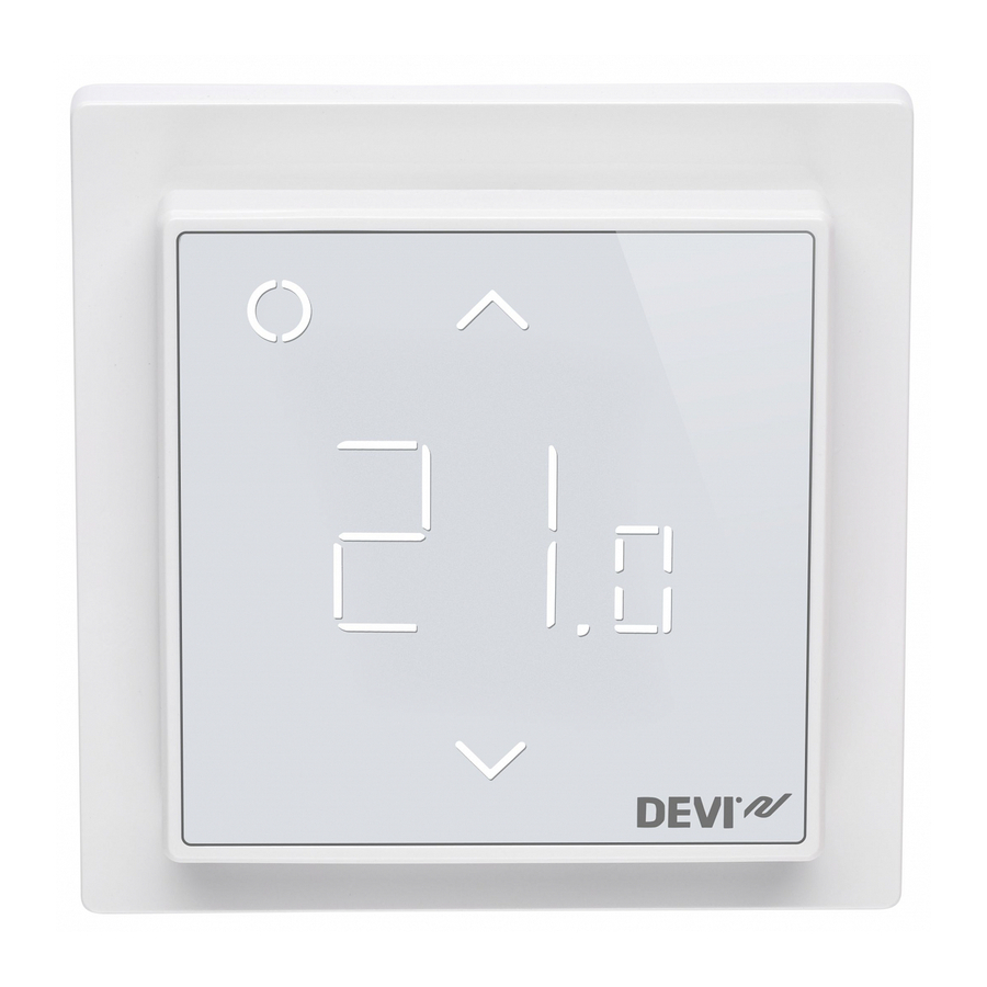
Page 12: Display Symbols
DEVIreg™ Smart Display Symbols Top part main functionalities are to support user interface through display and hold all the controller logic. Display main functionalities are to show the current status of the Thermostat and recognize the user actions from the buttons. - Page 13 DEVIreg™ Smart Nr� Type Description Button/Symbol Control button Button/Symbol Arrow Up button Button/Symbol Arrow Down button Symbol 3 digit 7 segment numbers with comma separator Symbol indications Indication Mode/State Description Blue - blinking Access Point Thermostat ready for set-up Mode Blue Access Point Smart phone connected...
- Page 14 DEVIreg™ Smart Green – Active Mode Thermostat waiting for confir- blinking & Access mation of action Point Mode Arrows – Active Mode Safety lock is on blinking rapidly when touched Interaction directly on thermostat Function Button Description Turn thermo- 1. Touch any Thermostat switch on stat on button...
- Page 15 DEVIreg™ Smart Frost protec- Touch and hold Deactivate frost protec- tion Control (1) for tion 1 sec. Safety lock Touch and hold Activate/Deactivate Up (2) + Down (3) safety lock for 3 sec. Factory restore Touch and hold Activates factory restore Control (1) + Up state (2) for 5 sec.
- Page 16 DEVIreg™ Smart Error Nr� Description Solu- Need restart type tion Floor Connection Contact The thermostat Sensor to sensor is service requires a restart discon- lost to operate again. nected Floor Sensor Contact The thermostat Sensor short- service requires a restart short- circuited to operate again.
-
Page 17: Configuring
DEVIreg™ Smart Configuring Download App Download the DEVIsmart™ app from App Store or Google Play or at devismart.com. Open the DEVIsmart™ App Follow instructions and set-up flow in the App. DEVIreg™ Smart indication The DEVIreg™ Smart shows “–” indicat- ing that power is ON, but still need to be configured. - Page 18 DEVIreg™ Smart display module, e.g. using a screw- driver; it will be possible to set the maximum floor temperature up to 45°. Furthermore, it will be possible to use only a room sensor. However, this option is not recom- mendable due to an increased risk of overheating the floor.
- Page 19 DEVIreg™ Smart Note: Please contact the floor supplier before changing the maximum floor temperature and be aware of the following: • The floor temperature is measured there, where the sensor is placed. • The temperature of the bottom of a wooden floor can be up to 10˚C higher than the top.
-
Page 20: Warranty
Warranty The products will, in the event of a fault that can be tracked back to a manufacturing defect in the DEVI product, be repaired or replaced free of charge. To apply for this warranty the installation must be performed by an authorized installer and the warranty certificate has to be stamped, signed and provided. -
Page 21: Disposal Instructions
DEVIreg™ Smart Disposal Instruction Installation Guide... - Page 22 DEVIreg™ Smart Installation Guide...
- Page 23 DEVIreg™ Smart Installation Guide...
- Page 24 This also applies to products already on order provided that such alterations can be made without subsequential changes being necessary in specifications already agreed. All trademarks in this material are property of the respective companies. DEVI and the DEVI logo-type are trademarks of Danfoss A/S. All rights reserved 0809xxxx &...
Need help?
Do you have a question about the DEVIreg Smart and is the answer not in the manual?
Questions and answers