DEVI devireg 530 Installation Manual
Hide thumbs
Also See for devireg 530:
- Installation instructions manual (12 pages) ,
- Instruction manual (20 pages) ,
- Installation instructions manual (10 pages)
Advertisement
Advertisement

Related Manuals for DEVI devireg 530


Summary of Contents for DEVI devireg 530
- Page 1 Installation Guide DEVIreg™ 530 Electronic Thermostat www.DEVI.com...
- Page 2 The English language is used for the original instructions. Other languages are a translation of the original instructions. (Directive 2006/42/EC)
-
Page 3: Table Of Contents
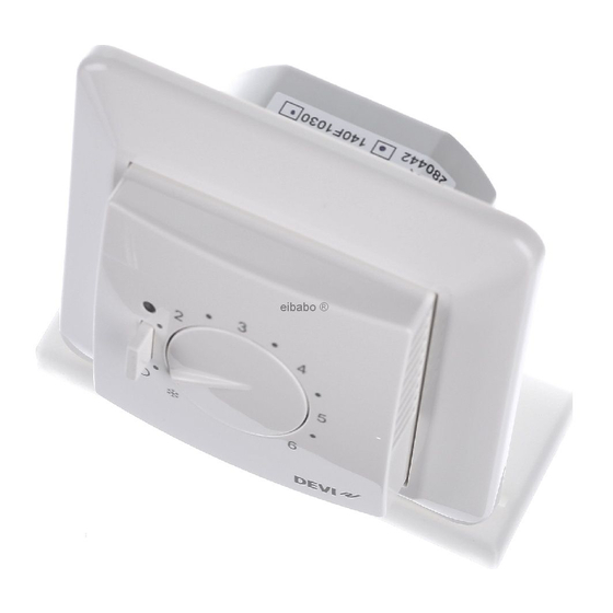
( ) 1 to 6 (each step corresponds to approximately 8°C). Furthermore, it has a LED indicator showing standby periods (green light) and heating periods (red light). More information on this product can also be found at: devireg.devi.com Installation Guide... -
Page 4: Technical Specifications
DEVIreg™ 530 Technical Specifications Operation voltage 220-240V~, 50Hz Standby power consump- Max 0.25W tion Relay: Resistive load Max 15A / 3450W @ 230V Inductive load cos φ= 0.3 max 1A Sensing units NTC 15kOhm at 25°C Sensing values: 0°C 42 kOhm 25°C 15 kOhm 50°C... -
Page 5: Safety Instructions
DEVIreg™ 530 Type Storage temperature -20 to +65°C IP class Protection class Class II - Dimensions 85 x 85 x 36mm Weight The product complies with the EN/IEC Standard "Automatic electrical controls for household and similar use": ▪ EN/IEC 60730-1 (general) ▪... -
Page 6: Mounting Instructions
DEVIreg™ 530 ▪ The installation of the thermostat must be done by an authorized and qualified installer according to local regulations. ▪ The thermostat must be connected to a power supply via an all-pole disconnection switch. ▪ The sensor is to be considered as live voltage. Have this in mind if the sensor must be extended. - Page 7 DEVIreg™ 530 Note: A floor sensor enables a more accu- rate temperature control and is recom- mended in all floor heating applications and mandatory under wooden floors to reduce the risk of over-heating the floor. ▪ Place the floor sensor in a conduit in an appropriate place where it is not exposed to sunlight or draft from door openings.
- Page 8 DEVIreg™ 530 Follow the steps below to mount the thermostat: 1. Open the thermostat: ▪ Press the release tab in the bottom of the ther- mostat using a flat object. ▪ Carefully detach the front cover. ▪ Carefully detach the frame. Installation Guide...
- Page 9 DEVIreg™ 530 2. Connect the thermostat according to the connection diagram. LOAD LOAD Mains Max. Load -5°C 220-240V~ 15 (1) A IP31 -10T30 D530 By connecting an external timer to the terminal marked by a moon symbol (and by using for example the same phase as for the mains power supply), the thermostat can be set to reduce the temperature by 5ºC during specified periods.
-
Page 10: Settings
DEVIreg™ 530 3. Mount and reassemble the thermostat. ▪ Fasten the thermostat to a socket or an exterior wall box by driving the screws through the holes in each side of the thermostat. ▪ Install the frame and front cover in the reverse or- der of disassembly. - Page 11 DEVIreg™ 530 ▪ Floor manufactures often specify the max temperature on the top surface of the floor (usually 27-28˚C). ▪ Always use a floor sensor to control floor heating. Without a floor sensor, the temperature control may be less accurate and you risk overheating the floor. Thermal Examples of floor- Details...
-
Page 12: Warranty
DEVIreg™ 530 Warranty Y E A R Disposal Instruction Installation Guide... - Page 13 DEVIreg™ 530 Installation Guide...
- Page 14 DEVIreg™ 530 Installation Guide...
- Page 15 This also applies to products already on order provided that such alterations can be made without subsequential changes being necessary in specifications already agreed. All trademarks in this material are property of the respective companies. DEVI and the DEVI logo- type are trademarks of Danfoss A/S.
Need help?
Do you have a question about the devireg 530 and is the answer not in the manual?
Questions and answers