
Related Manuals for DEVI Devireg 530 Series


Summary of Contents for DEVI Devireg 530 Series
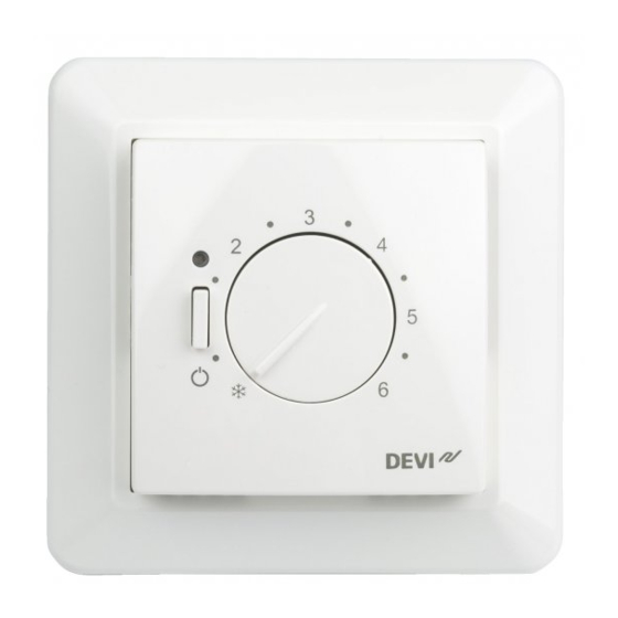
- Page 1 GB-DAS Installation Instructions – Devireg™ 530, 531, and 532 Installation Instructions Devireg 530, 531 and 532 Article: 08095821 Version: 01.01...
-
Page 2: Applications And Functions
Contents 1. Applications and Functions The installation must only be carried out by an The Devireg™ 530 series is a line of electronic Applications and functions authorised electrician. thermostats used for control of indoor heating. Maximum floor temperature setting Light indications (LED) The Devireg™... -
Page 3: Maximum Floor Temperature Setting
2. Maximum floor temperature setting 3. Light indications (LED) Maximum floor temperature is preset at the factory For wooden floor constructions DEVI™ recommend The is used for setting the thermostat in frost protec- The Devireg™ 530 series has a LED indicator above to 35°C for cable temperature safety. -
Page 4: Installation Instructions
If the supplied floor sensor is too short, longer ones To avoid cracks in the concrete floor you must ensure can be purchased from you local DEVI supplier or it can be extended with proper materials. that the floor is completely hardened before the heat is switched on. - Page 5 6. Placement of Devireg™ 530, 531, and 532 Installation height, typically between 80-150 cm., when Devireg™ 531/532 is used as room sensor. Not on a wall where it will be subjected to direct sunlight. In damp rooms it should be installed on an even surface, according to local building regulations.
- Page 6 7. Connection diagrams for Devireg™ 530, 531, and 532 Devireg™ 530 Devireg™ 531 Devireg™ 532 Temperature limiter NC = no connection NC = no connection NC = no connection...
-
Page 7: Troubleshooting
8. Trouble shooting Control of functioning 2) Mains voltage (terminal 1 and 3) 4) Heating cable (terminal 2 and 4) If the heat is not turned on by activating the ther- Measure the live supply voltage at terminal 1 and 3. Disconnect the heating cable from terminal 2 and 4 mostat, check the residual current device (RCD) The reading should be within specified range, accord-... - Page 8 8. Trouble shooting 5) External sensor input: NTC (only for Devireg™ 530 Fault: Constant heat Floor sensor interrupt and™532) Relay constantly on If disconnection of the external sensor (NTC) occurs, Disconnect the external NTC sensor 5 and 6 on the Measure the voltage at terminal 2 and 4, (non- the thermostat will be constant off...
- Page 9 9. Technical specifications for Devireg™ 530, 531, and 532 Operation voltage 230 VAC +10% / -20%, 50 Hz Temperature range: • 530 5-45°C Power consumption Max. 0.25W • 531 5-35°C Relays: • 532 5-35°C, floor temperature limiter range: 20-50° C •...
-
Page 10: Guarantee Certificate
All work will Please observe! 85/374/CEE as well as all applicable legislation in the individual be invoiced in full if DEVI is required to inspect or repair faults In order to obtain the DEVI ™...
Need help?
Do you have a question about the Devireg 530 Series and is the answer not in the manual?
Questions and answers