CAME V6000 Installation Manual
Hide thumbs
Also See for V6000:
- Installation manual (24 pages) ,
- Installation & operation manual (21 pages) ,
- Installation manual (17 pages)
Table of Contents
Advertisement
Available languages
Available languages
Advertisement
Table of Contents

Related Manuals for CAME V6000


Summary of Contents for CAME V6000
- Page 1 AUTOMAZIONE PER PORTE GARAGE MANUALE DI INSTALLAZIONE V6000...
- Page 2 Avvertimento (es. targa cancello). stato espressamente concepito. Ogni altro uso è da conside- Istruzioni e raccomandazioni rarsi quindi pericoloso. La CAME cancelli automatici s.p.a. non particolari per gli utenti è responsabile per eventuali danni causati da usi impropri, er- • Tenete libere da ingombri e pulite le aree di manovra del can- ronei ed irragionevoli •...
- Page 3 PAGINA LASCIATA INTENZIONALMENTE BIANCA PAGINA LASCIATA INTENZIONALMENTE BIANCA...
- Page 4 “IMPORTANTI ISTRUZIONI DI SICUREZZA PER L’INSTALLAZIONE” “ATTENZIONE: L’INSTALLAZIONE NON CORRETTA PUÒ CAUSARE GRAVI DANNI, SEGUIRE TUTTE LE ISTRUZIONI DI INSTALLAZIONE” “IL PRESENTE MANUALE È DESTINATO ESCLUSIVAMENTE A INSTALLATORI PROFESSIONALI O A PERSONE COMPETENTI” 1 Legenda simboli Questo simbolo indica parti da leggere con attenzione. Questo simbolo indica parti riguardanti la sicurezza.
- Page 5 A. Descrizione delle parti L'automazione per porte garage è composta di due confezioni: una per l'automazione e l'altra per la guida. Confezione automazione DESCRIZIONE Q.tà C ON FEZION E BU LLON ER I A Automazione Vite autoforante a testa 6 x 15 (8x) esagonale Manuale...
- Page 6 C. Assemblaggio IMPORTANTI INDICAZIONI DI SICUREZZA PER L’INSTALLAZIONE Questo prodotto deve essere destinato solo all’uso per il quale è stato espressamente studiato. Ogni altro uso è da considerarsi improprio e quindi pericoloso. • Prima di procedere all’installazione dell’automazione, rimuovere corde o imballi non necessari e disattivare i dispositivi che risulteranno non necessari dopo l’installazione dell’automazione.
- Page 7 C-3 Fissaggio alla porta Muro 30° Staff a di testa Vite M6x80 con dado Piattina forata di fi ssaggio Piattina forata di fi ssaggio Porta Vite a espansione Vite di regolazione Staff a porta Staff a a U Supporto Vite M6x15 staff a Vite a espansione...
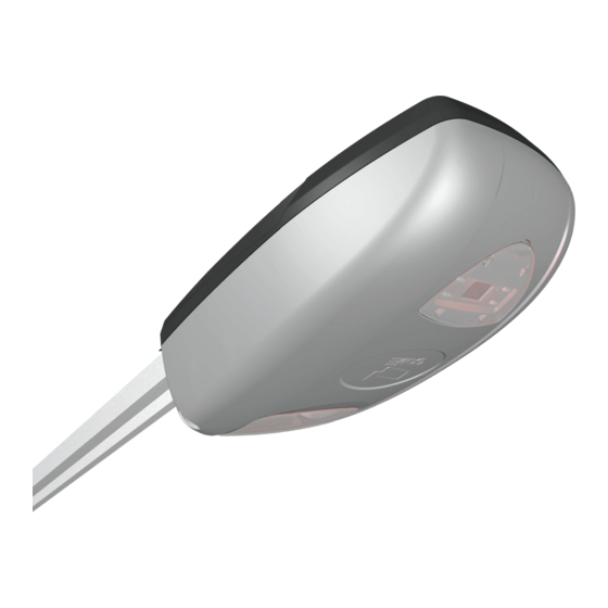
- Page 8 D. Descrizione automazione e display D. The Main Body and Program Panel Luce garage Coperchio display Indicatore attività del radiocomando Tasto per la Tasto per la regolazione codifi ca Funzioni Regolazioni Indicatore attività di programmazione e di funzionamento E. Collegamento fotocellule a) Collegamenti Schema collegamento Scheda elettronica...
- Page 9 F. Programmazione Preparazione a. Muovere la porta manualmente fino all’aggancio del carrello per la movimentazione automatica. b. Alimentare l’automazione. Dopo un segnale acustico, la scheda è pronta per la programmazione. Attenzione: in ogni fase successiva, bisogna completare la programmazione altrimenti il settaggio sarà cancellato automaticamente.
- Page 10 F-3 Memorizzazione corsa La porta raggiunge il fi necorsa di Premere “-”, appare “3” Premere “P”, “3” lampeggia apertura apre automaticamente Premere nuovamente “P” La porta raggiunge il Premere “P” per salvare fi necorsa di chiusura le informazioni F-4 Settaggio del livello di forza Il livello di default settato in fabbrica è...
- Page 11 F-6 Settaggio dell'allarme Premere “-”, appare “6” Premere “P”, appare 0 Permere “+”, appare 1: (OFF, settaggio di default) l'allarme è attivo (ON) Con allarme attivo, l'automazione emetterà un segnale acustico se la porta rimane aperta per più di 10 minuti. Il segnale avrà una durata di 30 secondi ogni 10 minuti. Per far cessare l’allarme, chiudere completamente la porta.
- Page 12 F-8 Funzione Contamanovre Questa funzione serve ad attivare un segnale acustico dopo 2000 cicli di funzionamento. Premere “P”, appare 0 Premere “+”, appare 1: la Premere “-”, appare “8” (OFF, settaggio di default) funzione è attiva (ON) Verificare regolarmente che la porta sia livellata e bilanciata sia in apertura che in chiusura, e che la molla, da sola, sia sufficiente per aprire la porta.
- Page 13 Attenzione! a ogni successiva modifi ca anche di una sola delle fasi di programmazione (es.: F-4 Settaggio del livello di forza), ripetere la convalida. I. Dati tecnici e limiti d’impiego I-1 Automazione SUPERFICIE DELLA TEMPERATURA DI MODELLO VOLTAGGIO PORTA FUNZIONAMENTO V6000 220-240 V ≤ 10 m2 - 20 / + 55 °C I-2 Guide MODELLO LUNGHEZZA TOTALE CORSA ALTEZZA PORTA V06001...
- Page 14 I. Guida per l’utente finale I-1 Manutenzione dell’automazione a) L’automazione V6000 è prodotta nel rispetto dell’ambiente e richiede una manutenzione periodica ridotta. b) Per la prima manovra, verificare che il sistema di trasmissione si muova con facilità (sbloccare il dispositivo, spingere e tirare la porta manualmente).
- Page 15 UNI EN ISO 14001 a garanzia del rispetto e della tutela dell’ambiente. Vi chiediamo di continuare l’opera di tutela dell’ambiente, che CAME considera uno dei fondamenti di sviluppo delle proprie strate- gie operative e di mercato, semplicemente osservando brevi indicazioni in materia di smaltimento: SMALTIMENTO DELL’IMBALLO...
- Page 16 127273, Moscow Moscow Moscow (+34) 91 46 85 442 (+7) 495 739 00 69 (+7) 495 739 00 69 (ext. 226) CAME United Kingdom Ltd. CAME United Kingdom Ltd. CAME United Kingdom Ltd. GREAT BRITAIN PORTUGAL CAME Portugal CAME Portugal...
- Page 17 AUTOMATION FOR GARAGE DOORS INSTALLATION MANUAL V6000...
- Page 18 Warning Sings (e.g. gate plate). (i.e. that for which it was expressly built for). Any other use is Special instructions and to be considered dangerous. Came Cancelli Automatici S.p.A. advice for users is not liable for any damage resulting from improper, wrongful •...
- Page 19 THIS PAGE LEFT INTENTIONALLY BLANK THIS PAGE LEFT INTENTIONALLY BLANK...
- Page 20 "IMPORTANT INSTALLATION SAFETY INSTRUCTIONS" “WARNING: IMPROPER INSTALLATION MAY RESULT IN SERIOUS HARM. PLEASE FOLLOW ALL INSTALLATION INSTRUCTIONS” “THIS MANUAL IS INTENDED ONLY FOR PROFESSIONAL INSTALLERS OR OTHER COMPETENT INDIVIDUALS” Legend of symbols This symbol shows parts which must be read with care. This symbol means the parts which describe safety issues.
- Page 21 A. Description of parts The automation for garage doors is composed of two packages, the first for the operator and the second for the guide. Operator package DESCRIPTION Q.ty PAC K AGE O F N U TS AN D S C R EWS Operator Self-tapping hexagonal- 6 x 15...
- Page 22 C. Assembly IMPORTANT INSTALLATION SAFETY INSTRUCTIONS This product is only intended to be used for the purpose it was designed. Any other use is therefore improper and dangerous. Before beginning to install, do the following: • Remove cords or unnecessary packagins and deactivate all the decives that won’t be necessary after the installation. •...
- Page 23 C-3 Fastening to the door Wall 30° M6x80 screw Head bracket with nut Perforated anchoring bracket Perforated anchoring plate Door Screw expansion Adjusting screw Door bracket U-shaped bracket Bracket support M6x15 screw 8 x 20 screw Expansion screw 8 X 20 screw 8 x 25 inserter Curved arm C-4 Manually opening the door...
- Page 24 D. Description of the operator and screen Garage light Screen cover Transmitter activity indicator Button for Setting button memorising codes Functions Settings Programming and operation activity indicator E. Connecting photocells a) Connections Wiring diagram Control board Photocell...
- Page 25 F. Programming Setting up a. Manually move the door until the castor latches for automatic moving. b. Power up the operator. After a sound signal, the card is ready to be programmed. Warning: in each subsequent phase, programming must be completed, otherwise the setting will automatically be cancelled.
- Page 26 F-3 Memorising the door run The door reaches the opening Press “-”, "3" appears Press “P”, “3” starts fl ashing endpoint automatically Press “P” again The door reaches Press “P” " to save the the closing endpoint information F-4 Setting the force level The factory default setting level is 4;...
- Page 27 F-6 Setting the alarm Press “-”, "6" appears Press “P”, 0 appears Press "+", 1 appears: (OFF, Default setting) the alarm is active (ON) With alarm active, the automation will issue a sound signal if it stays open for more than 10 minutes.
- Page 28 F-8 Door-Run-Counter Function This function is for activating a sound warning after 2000 working cycles. Press “P”, 0 appears Press “+”, 1 appears: Press “-”, 8 appears (OFF, Default setting) function is active (ON) Regularly check that the door is levelled and balanced both when opening and closing and that the spring alone allows the door to open.
- Page 29 Warning! after every subsequent modifi cation of even one single programming phase (ex.: F-4 Setting the force level), repeat the validation. I. Technical specifications and limits to use I-1 Operator DOOR SURFACE OPERATING MODEL VOLTAGE TEMPERATURE V6000 220-240 V ≤ 10 m2 - 20 / +55°C I-2 Guide MODEL TOTAL LENGTH DOOR RUN DOOR HEIGHT...
- Page 30 J-1 Maintenance of the automation a) The V6000 operator is made to be environmentally friendly and requires little periodic maintenance. b) The first time, check that the transmission system moves easily (release the device, push and pull the door manually).
- Page 31 UNI EN ISO 14001 standard to ensure environmental protection. Please help us to safeguard the environment. At CAME we believe this to be one of the fundamentals of ours market operations and development strategies. Just follow these short disposal instructions: DISPOSING OF THE PACKAGING The components of the packaging (i.e.
- Page 32 127273, Moscow Moscow Moscow (+34) 91 46 85 442 (+7) 495 739 00 69 (+7) 495 739 00 69 (ext. 226) CAME United Kingdom Ltd. CAME United Kingdom Ltd. CAME United Kingdom Ltd. GREAT BRITAIN PORTUGAL CAME Portugal CAME Portugal...
Need help?
Do you have a question about the V6000 and is the answer not in the manual?
Questions and answers