Table of Contents
Advertisement
Quick Links
Requires : 3 - channel radio w/ 2 micro servos,
Wing Span
Wing Area
Flying Weight
Fuselage Length
Warning ! This model is not a toy.
It is designed for maximum performance. Please seek advice if one is not familiar with this kind
of electric powered precision model. Operating this model without prior preparation may cause
injuries. Remember, safety is the most important thing. Always keep this instruction manual at
hand for quick reference.
E182NXMPO25961107
Outrunner Motor KM0283010
w/ Propeller Adaptor HW23 40100
15A Brushless ESC,2 cells 7.4V
1000 mAh Li-Po battery & charger.
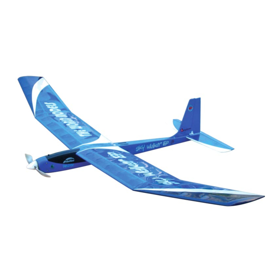
Specifications
*Specifications are subject to change without notice.*
INSTRUCTION MANUAL
63.0 in / 1600 mm
420 sq in / 27 sq dm
17
oz /
480
g
3 in / 8
3
35
mm
ALMOST-READY-TO-FLY (ARF) SERIES
FACTORY PRE-FABRICATED
MADE IN CHINA
Advertisement
Table of Contents

Related Manuals for THE WORLD MODELS Sky Walker EP


Summary of Contents for THE WORLD MODELS Sky Walker EP
- Page 1 INSTRUCTION MANUAL Requires : 3 - channel radio w/ 2 micro servos, Outrunner Motor KM0283010 w/ Propeller Adaptor HW23 40100 15A Brushless ESC,2 cells 7.4V 1000 mAh Li-Po battery & charger. Specifications 63.0 in / 1600 mm Wing Span 420 sq in / 27 sq dm Wing Area oz / Flying Weight...
-
Page 2: Before You Begin
I N D E X BEFORE YOU BEGIN P. 1 PARTS LIST P. 2 ASSEMBLY P. 3 -9 SAFETY PRECAUTIONS BEFORE YOU BEGIN Apply instant glue Apply epoxy glue. (C.A.glue, super glue.) Must be purchased separately! Apply thread locker Assemble left and right Ensure smooth non-binding sides the same way. -
Page 3: Parts List
Parts list 1. MAIN WING -- 1 pair. WING JOINER Ø4.5 x 161 mm -- 1 pc. 9. CANOPY -- 1 set 2. FUSELAGE -- 1 pc. 10. DECALS E182NXMDEC -- 1 set STABILIZER & ELEVATOR -- 1 set COVERING: 3. -
Page 4: Stabilizer & Elevator
Main Wing Wing Joiner Ø4.5 x 161mm Completed Stabilizer & Elevator Apply instant type CA glue to both sides of each hinge. Bottom View Temporary install the main wing, adjust (Stabilizer) leveling of the stabilizer to make it as parallel to the main wing as possible. (Main Wing) *Also refer to step 10 Wing Setting A A'... - Page 5 Vertical Fin / Rudder Apply instant type CA glue to both sides of each hinge. Peel off shaded Portion covering film. Completed E182NXMPO25961107...
-
Page 6: Elevator Pushrod
Elevator Pushrod Ø1mm pilot holes for World Models tri-horn are pre-drilled. Please look for pin-hole marks at under side of control Screw PB2x8mm surfaces. PB2x8mm Clevis Fuel Tube d2xD4x4mm Pushrod Horn 1.4x486mm TWM PL8210010 CLEVIS WRENCH Bottom View Rudder Pushrod Ø1mm pilot holes for World Models tri-horn are pre-drilled. -
Page 7: Optional Parts
Motor / Cowling Setting KP0011310 Solder Solder Optional Parts M x mm Sock Head Screw M3x6mm Socket Head Screw PM2x12mm Screw PWA2x8mm Screw Outrunner Motor 28/ 30 PA2.6x8mm Screw KM0283010 d3xD7mm Washer d3xD7mm Washer Don't over-tighten the PM3 screws, too much Propeller Adaptor stress on the screws (d3xD5) HW2340100... -
Page 8: Radio Equipment
Radio Equipment Install and arrange the servo as shown in the diagram. Elevator Servo Battery Tie Elevator Pushrod Front Straper Sponge Double-Sided Tape Battery Rudder Servo Fuel Tube Brushless ESC Rudder Pushrod D2XD4X4mm Main Wing Screw PM2.5x16mm Washer d2.6xD9mm PM2.5 x 16mm d2.5 x D8mm Wing Protection 0.8 x 25 x 61mm... -
Page 9: Control Throws
Wing Setting Adjust the wing and fuselage configuration as shown in the diagrams. A=A' B=B' C=C' Control Throws Adjust the control throws as shown in the diagram. These throws are good for general flying. You can adjust according to your Rudder 25mm personal preference. - Page 10 The ideal C.G. position is 53mm (2.1 in.) ehind the leading edge C.G. measured at where the wing meets the fuselage. In order to obtain the C.G. specified, add weight to the fuselage or move the battery position. Check the C.G. Before flying. http://www.theworldmodels.com/para/instruction/instructionManuals.php Warning! Important Safety Precautions...
- Page 11 Pl8210010 Large Clevis Small Clevis E182NXMPO25961107...
- Page 12 The World Models Manufacturing Co., LTD. www .thew orldm odels .com E182NXMPO25961107...
Need help?
Do you have a question about the Sky Walker EP and is the answer not in the manual?
Questions and answers