Table of Contents
Advertisement
Quick Links
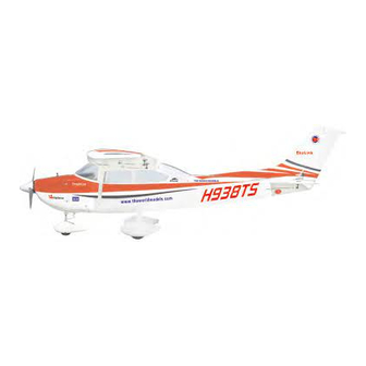
SkyLink 40
0.40-0.55 cu. in. displacement 2-stroke
Requires : 5-channel radio w/ 7 standard servos
Wing Span
Wing Area
Flying Weight
Fuselage Length
Warning! This model is not a toy.
It is designed for maximum performance. Please seek advice if one is not familiar with this kind
of engine powered precision model. Operating this model without prior preparation may cause
injuries. Remember, safety is the most important thing. Always keep this instruction manual at
hand for quick reference.
The World Models
Manufacturing Co., Ltd.
www.theworldmodels .com
A246PO28151211
Specifications
*Specifications are subject to change without notice.*
66 in / 1680 mm
590 sq in / 38.1 sq dm
6.6 Ibs / 3000 g
51 in / 1300 mm
FACTORY PRE-FABRICATED
ALMOST-READY-TO-FLY (ARF) SERIES
INSTRUCTION MANUAL
MADE IN CHINA
Advertisement
Table of Contents

Related Manuals for THE WORLD MODELS SkyLink 40


Summary of Contents for THE WORLD MODELS SkyLink 40
- Page 1 INSTRUCTION MANUAL SkyLink 40 0.40-0.55 cu. in. displacement 2-stroke Requires : 5-channel radio w/ 7 standard servos Specifications Wing Span 66 in / 1680 mm Wing Area 590 sq in / 38.1 sq dm Flying Weight 6.6 Ibs / 3000 g...
- Page 2 SkyLink 40 INDEX BEFORE YOU BEGIN PARTS LIST ASSEMBLY P.3-P.12 SAFETY PRECAUTIONS P.12 BEFORE YOU BEGIN Read through the manual before you begin, so you will have an overall idea of what to do. Check all parts. If you find any defective or missing parts contact your local dealer. Please DRY FIT and check for defects for all parts that will require CA or Epoxy for final assembly.
- Page 3 Parts List 1. MAIN WING -- 1 pair PLASTIC TUBE d2xD3x140mm -- 1 pc. FRONT WHEEL PUSHROD Ø1.4x260mm -- 1 pc. 2. SCREW PB2x20mm -- 4 pcs PLASTIC TUBE d2.5xD4x140mm -- 1 pc. SCREW PB2x16mm -- 2 pcs SCREW PB2x22mm -- 4 pcs 12.
- Page 4 Main Wing Apply instant type CA glue to both sides of each hinge. Aileron Servo Lead Bottom View Ø1mm pilot holes for World Models tri-horn are pre-drilled. Aileron & Flap Servos Please look for pin-hole marks at under side of control surfaces. PB2x20mm Screw PB2x16mm PB2x20mm...
- Page 5 Main Wing Please dry fit wing joiner into left and right wing to make sure they fit with the proper dihedral angle, mark the wing joiner if necessary. Apply epoxy glue to both sides of all surfaces in contact. Use a stick to apply the glue to inner side of wing joiner sleeve, and apply the glue to wing joiner before putting them together.
-
Page 6: Elevator Pushrod
Vertical Fin & Rudder Apply instant type CA glue to both sides of each hinge. Remove coverings for all surfaces in c = c' contact before applying A/B epoxy glue. Completed Elevator Pushrod TWM PL8210010 CLEVIS WRENCH Ø1mm pilot holes for World Models horn are pre-drilled. PB2x16mm Screw Please look for pin-hole marks at under side of control surfaces. - Page 7 Engine Mount M4x25mm Socket Head Screw Engine Mount PL5111050 d4xD9mm Washer Blind nuts are off-centered to keep the spinner at the fuselage axis. d4xD9mm Washer M4x25mm Socket Head Screw Front Landing Gear 4.1mm Collar M3x3mm Set Screw 4.1mm Wheel Collar Ø50mm 4.1mm M3x3mm...
-
Page 8: Fuel Tank
Fuel Tank DOUBLE-SIDED TAPE 40x100mm 380cc CABLE TIE 1.5x5x400mm Fuel Tank 380cc Engine M3x25mm Socket Head Screw d3xD7mm Washer M3 Nut M3x25mm Installed Engine Position 127 mm d3xD7mm 5.0 in. Washer M3 Nut Front Wheel Pushrod Ø1.4x260mm Plastic Tube Plastic Tube d2.5xD4x140mm Throttle Pushrod d2xD3x140mm... -
Page 9: Main Landing Gear
Main Landing Gear HM4x45mm Screw Wheel Ø62mm KA2.3x8mm Screw M2.5x16mm Set Screw d4xD9mm Washer HM4x45mm d2xD8mm Quick Release Nylon Rivet M2.5x16mm Socket Head Screw M4 Nut d2.5xD8mm M4 Nut 4.1mm Plate 1mm Washer Collar d4xD9mm Washer d2xD8mm Quick Release Nylon Rivet d2.5xD8mm Washer Wheel Pant... -
Page 10: Radio Equipment
Radio Equipment J1(Pushrod Ø1.8x100mm) Install and arrange the servos as shown in the diagram. J2(Pushrod Ø1.8x650mm) Rudder Pushrod Front Wheel Pushrod Elevator Pushrod Front Ø1.8x760mm Ø1.4x260mm Ø1.8x100mm M2 Nut Rudder Servo Receiver Straper KM2x8mm Pushrod Connector Fuel Tube Ø6x5mm Battery Elevator Pushrod Elevator Servo Ø1.8x635mm... - Page 11 Cowling & Spinner First insert the grommet to the cowling then apply screw. PWA2.6x12mm Screw Fuselage Cowling d1.5xD6.5mm Silicon Grommet Spinner Ø52mm PWA2.6x12mm Please refer to the d1.5x6.5mm attached sheet for Silicon Grommet usage of the transparent 3D template. Bottom View Wing Struts HM2.5x16mm Screw Battery Cover...
- Page 12 Wing Setting Adjust the wing and fuselage configuration as shown in the diagrams. A’ B’ C’ D’ A=A' B=B' C=C' D=D' A246PO28151211 P.11...
-
Page 13: Control Throws
# First time flyer should never fly by himself / herself. Assistance from experienced flyer is absolutely necessary. # Pre-flight adjustment must be done before flying, it is very dangerous to fly a badly pre-adjusted aircraft. SkyLink 40 is specially designed to be powered by 2C 0.40-0.55 engine, using a more powerful engine does not mean better performance. - Page 14 LINKAGE CONNECTOR HW7111050 & HW7111060 Drill 2mm hole at servo horn. Insert linkage connector into servo horn. Make sure shoulder of screw is cleared from servo horn. Add washer to reduce play if necessary. Shoulder Tighten up the round nut against the shoulder.
- Page 15 Usage of the transparent 3D template This transparent 3D template is used for position guidance of the actual cutting of the pre-painted cowling. Simply cut the transparent 3D template to fit your engine and exhaust pipe, then slide onto the actual cowling and use as template to mark the openings required for final cutting.
- Page 16 The World Models Manufacturing Co., Ltd. www.theworldmodel s.com A246PO28151211...
Need help?
Do you have a question about the SkyLink 40 and is the answer not in the manual?
Questions and answers