Table of Contents
Advertisement
Quick Links
0.40-0.50 cu.in. displacement 2-cycle
0.52 cu.in. displacement 4-cycle
Radio required : 4 channel
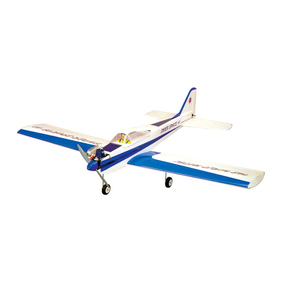
Wing Span
Wing Area
Flying Weight
Fuselage Length
Warning !This model is not a toy.
It is designed for maximum performance. Please seek advice if one is not familiar with this kind
of engine powered precision model. Operating this model without prior preparation may cause
injuries. Remember, safety is the most important thing. Always keep this instruction manual at
hand for quick reference.
The World Models
Manufacturing Co., LTD.
www .thew orldm odels .com
-
Specifications
* Specifications are subject to change without notice.*
radio w / 4 standard
56.0in / 1420mm
565 sq in / 36.5 sq dm
5.5 lbs / 2500 g
48.0 in / 1220mm
ALMOST-READY-TO-FLY (ARF) SERIES
INSTRUCTION MANUAL
servos
FACTORY PRE-FABRICATED
MADE IN CHINA
Advertisement
Table of Contents

Subscribe to Our Youtube Channel
Related Manuals for THE WORLD MODELS Super Sport 40


Summary of Contents for THE WORLD MODELS Super Sport 40
- Page 1 Operating this model without prior preparation may cause injuries. Remember, safety is the most important thing. Always keep this instruction manual at hand for quick reference. FACTORY PRE-FABRICATED The World Models ALMOST-READY-TO-FLY (ARF) SERIES Manufacturing Co., LTD. MADE IN CHINA...
-
Page 2: Before You Begin
I N D E X BEFORE YOU BEGIN P. 1 PARTS LIST P. 2 ASSEMBLY P. 3 - 10 SAFETY PRECAUTIONS P. 11 BEFORE YOU BEGIN Read through the manual before you begin, so you will have an overall idea of what to do. Check all parts. - Page 3 Parts List 1. MAIN WING -- 1 pair SCREW PB2x12mm -- 3 pcs TRI-HORN M3x22mm (S) -- 1 set 2. RING 2.3mm (For Aileron) -- 2 pcs Ø CLEVIS -- 1 pc. 3. WOODEN Wing Joiner 6x16x84mm -- 1 pc. FUEL TUBE Ø6x5mm -- 1 pc.
- Page 4 Pre-glued Pre-glued Cut out to fit in the aileron servo. Apply glue to both sides of all surfaces in contact. Use a stick to apply glue to inner side of wing joiner sleeve, and apply glue to wing joiner before putting them together.
-
Page 5: Bottom View
Cut out to fit in the aileron servo. Plywood Bottom View 3 x 45 x 90mm Straper Fuel Tube 6x5mm Clevis Ring P. 4... -
Page 6: Main Landing Gear
Main Landing Gear PA3 x 12mm Plate Main Landing Gear 3.1mmCollar 3mmSet Screw Stabilizer & Elevator PM3 x 22mm PM3 x 25mm PM 3 x 22mm Screw d3xD12mm d3 x D12mm PM 3 x 25mm Screw d3 x D12mm Washer Bottom View P. - Page 7 Vertical Fin & Rudder 320cc M3x22mm Socket Head Screw P. 6...
-
Page 8: Rudder Pushrod
3mm Set Screw 4.1mm Collar 3mm Set Screw Completed Front View If the engine throttle control is on the opposite side, install the throttle pushwire accordingly. Install the throttle servo with the M3x25mm Socket Head Screw drive pinion on the same side of throttle pushwire. -
Page 9: Elevator Pushrod
Elevator Pushrod Ø1mm pilot holes for World Models tri-horn are pre-drilled. Please look for pin-hole marks at under side of control surfaces. PB 2x14mm Screw Elevator Tri-horn PB2 x 14mm Fuel Tube Pushrod 1.8 x745mm Tri-horn M3 x 14mm Servo Set LINKAGE CONNECTOR 3 x 3mm Set Screw Linkage Connector... - Page 10 Silicon Grommet d1.5 x D6.5mm PWA2.3 x 8mm Apply double-sided tape Pilot M3x 22mm d3 x D12mm M3 x 22mmSocket Head Screw d3 x D12mm Washer Bottom View Adjust the wing and fuselage configuration as shown in the diagrams. A = A' B = B' C = C' P.
- Page 11 Adjust the control throws as shown in the diagram. These throws are good for general flying. You can adjust according to your personal preference. Elevator 12mm 12mm Rudder 20mm 20mm Aileron The ideal C.G. Position is 78mm (3.07 in) behind the leading edge measured at where the wing meets the fuselage.
-
Page 12: Important Safety Precautions
Important Safety Precautions First time flyer should never fly by himself / herself. Assistance from experienced flyer is absolutely necessary. Pre-flight adjustment must be done before flying, it is very dangerous to fly a badly pre-adjusted aircraft. is specially designed to be powered by 2C 0.40 - 0.50 or 4C 0.52 engine, using a more powerful engine does not mean better performance. - Page 13 LINKAGE CONNECTOR HW7111050 & HW7111060 Drill 2mm hole at servo horn. Insert linkage connector into servo horn. Make sure shoulder of screw is cleared from servo horn. Add washer to reduce play if necessary. Shoulder Tighten up the round nut against the shoulder.
- Page 14 Product Registration Form (US Customers) We would like to share with you any relevant information regarding your model, including product news and free upgrade parts when applicable. Please fill in the following and send to Air orne Models, 4749-K,Bennett Drive, Livermore, CA 94551 USA 1.Name: 2.Address: 3.Phone #:...
-
Page 15: Optional Parts
Optional Parts ACCESSORIES) Fuel Filler 180mm Extension Code No. Size Package Code No. Size Package PL8110030 KW0011800 180mm 1 set 15 x 22 x 49mm 1 x 1 pc 180mm Y-Cord Package Code No. Size KW0021800 180mm 1 pc Clevis Wrench Code No. - Page 16 The World Models Manufacturing Co., LTD. www .thew orldm odels .com A049PO22351029...
Need help?
Do you have a question about the Super Sport 40 and is the answer not in the manual?
Questions and answers