Osburn 2000 Owner's Manual
Freestanding wood stove
Hide thumbs
Also See for OSBURN 2000:
- Installation and operation manual (64 pages) ,
- Owner's manual (39 pages) ,
- Installation and operation manual (60 pages)
Table of Contents
Advertisement
Quick Links
OWNER'S MANUAL
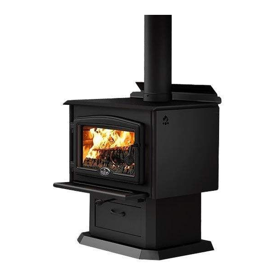
OSBURN 2000 FREESTANDING WOOD STOVE
US ENVIRONMENTAL PROTECTION
AGENCY PHASE II CERTIFIED
WOOD INSERT
Verified and tested following
ULC S627 and UL 1482 Standards
by:
STOVE BUILDER INTERNATIONAL INC.
250, de Copenhague, Saint-Augustin-de-Desmaures (Quebec), Canada G3A 2H3
Tel: (418) 878-3040 Fax: (418) 878-3001
www.osburn-mfg.com
READ AND KEEP THIS MANUAL FOR REFERENCE
This manual is available for free download on the manufacturer's web site. It is a copyrighted
document. Re-sale is strictly prohibited. The manufacturer may update this manual from time
to time and cannot be responsible for problems, injuries, or damages arising out of the use of
information contained in any manual obtained from unauthorized sources.
45270A
Printed in Canada
20-06-2011
Advertisement
Table of Contents

Related Manuals for Osburn OSBURN 2000


Summary of Contents for Osburn OSBURN 2000
- Page 1 OWNER’S MANUAL OSBURN 2000 FREESTANDING WOOD STOVE US ENVIRONMENTAL PROTECTION AGENCY PHASE II CERTIFIED WOOD INSERT Verified and tested following ULC S627 and UL 1482 Standards STOVE BUILDER INTERNATIONAL INC. 250, de Copenhague, Saint-Augustin-de-Desmaures (Quebec), Canada G3A 2H3 Tel: (418) 878-3040 Fax: (418) 878-3001 www.osburn-mfg.com...
- Page 2 Keep your sales invoice. We also recommend that you register your warranty online www.osburn-mfg.com Registering your warranty online will help us track rapidly the information we need on your stove.
-
Page 3: Table Of Contents
GLASS ........................... 32 GASKETING ......................... 33 ASH REMOVAL USING THE ASH DRAWER ............33 CHIMNEY (FLUE) CLEANING ................... 34 BAFFLE INSTALLATION .................... 35 SECONDARY AIR TUBE REPLACEMENT ............... 36 SECTION 5.0 SPECIFICATIONS ..................... 37 OSBURN LIMITED LIFETIME WARRANTY ..............38... -
Page 4: Section 1.0 - Installation
SECTION 1.0 - INSTALLATION When installed and operated as described in these instructions, the Osburn 2000 wood stove is suitable for use as a freestanding wood stove in residential installations. The E.P.A Osburn wood stove is not intended for installation in a bedroom. -
Page 5: Door Overlay Installation
1.1.2 Door overlay installation In order to complete the assembly of your freestanding Osburn 2000 wood stove, you need to install the door overlay. See table 1.1.3 below for installation instructions : 1- Position the overlay on the door frame and fix it in place from behind using the 4 screws. -
Page 6: Clearances To Combustibles And Floor Protector
CLEARANCES TO COMBUSTIBLES AND FLOOR PROTECTOR To install your appliance correctly, it is extremely important to respect all clearances to any combustibles as indicated on your stove’s certification label. Clearances to combustible materials (see figure 1.3 to match each letter to a clearance) CLEARANCES (SINGLE WALL PIPE) CANADA 14"... - Page 7 FIGURE 1.3 Clearances to combustible materials and floor protection...
- Page 8 Floor protector If the stove is to be installed on top of a combustible floor, it must be guarded by a non combustible material as shown on figure 1.3 (see the dotted line area). FLOOR PROTECTOR* CANADA 8’’ (205 mm) – Note 1 N/A (Canada only) 8’’...
- Page 9 Reducing Clearances With Shielding TYPE OF PROTECTION Sides and Rear/Back Sheet metal, a minimum of 0,024" (0,61mm) spaced out at least 1" (25mm) by non-combustible spacers (see graphic 2). Ceramic tiles, or an equivalent non-combustible material on fire-proof supports spaced out at least 1" (25 mm) by non- combustible spacers (see graphic 3).
- Page 10 Graphic 1 A- Minimum clearance required between the appliance and an unshielded combustible ceiling. B- 20 in. (500 mm) minimum; C- 1 in. (25 mm) minimum; D- Between 1 in. and 3 in. (25 mm and 75 mm); E- 3 in.(75 mm) minimum; F- 18 in.
- Page 11 Graphic 2 A- 1 in.(25 mm) minimum; 1- Combustible wall; 2- Non-combustible spacers; 3- 0.024’’ (0.61mm) sheet metal. Graphic 3 A- 1 in. (25 mm) minimum; 1- Combustible wall; 2- Non-combustible spacers; 3- Non-combustible support; 4- Ceramic tile or non-combustible material. Graphic 4 A- 1 in.
- Page 12 Graphic 5 A- 1 in. (25 mm) minimum; 1- Combustible wall; 2- Non-combustible spacers; 3- Brick. Graphique 6 A- 1 in. (25 mm) minimum; 1- Combustible wall; 2- Non-combustible spacers; 3- 0.024’’ (0.61 mm) thick sheet metal; 4- Brick.
-
Page 13: Section 2.0 Chimney (Flue System)
SECTION 2.0 CHIMNEY (FLUE SYSTEM) DEFINITIONS For clarity, the following definitions should be used with respect to these instructions: A chimney system consists of a connector off the top of the stove, and a chimne , which attaches to the connector and terminates outside the house. A chimney can be a masonry chimney (of masonry construction with an inside liner), or a factory built chimney. - Page 14 If you are using a masonry chimney, it is important that it be built in compliance with the specifications of the Building Code. It must be lined with fire clay bricks, or clay tiles, sealed together with fire cement, or have a listed solid fuel burning stainless steel liner. Round chimneys are the most efficient.
-
Page 15: Step By Step Installation Of Your Factory-Built Chimney
FIGURE 2.2 Minimum Height of the Chimney 2.2.1 Step by step installation of your factory-built chimney The way to install your chimney may vary from one chimney manufacturer to another. For installation instructions, we advise you to consult your chimney manufacturer whose products are sold at many North American retailers of wood stoves and related heating accessories. - Page 16 Typical installation through the wall Wall support system If your chimney must rise along an outside wall, you need to connect it to your stove through an adjacent wall. For this type of installation, the following items are normally required : Chimney Suitable lengths of chimney (enough to go up to your roof) An adjustable wall support...
- Page 17 Typical installation through the ceiling Ceiling support system If your chimney must rise inside the house and go through the ceiling, you need to connect it to your stove at the ceiling level. For this type of installation, the following items are normally required : Chimney An adequate number of chimney sections (enough to go up to your roof) A ceiling support kit with stove pipe adapter...
-
Page 18: Typical Installation Through An Existing Masonry Chimney
2.2.2 Typical installation through an existing masonry chimney You can also install your stove using your existing masonry chimney. To do so, follow the guidelines below. You may want to use a factory-built thimble, on construct your own brick thimble. If you are using a masonry chimney, it is important that it be built in compliance with the specifications of the Building Code in your region. - Page 19 FIGURE 2.2.2 (B) Factory Built Thimble...
- Page 20 FIGURE 2.2.2 (C) Brick Thimble...
-
Page 21: Chimney Connector
CHIMNEY CONNECTOR Your chimney connector (commonly called stove pipe) and chimney must have the same diameter as the stove’s exhaust outlet. The stove pipe must be made of aluminized or cold roll steel with a minimum 24-gauge thickness (0.021" or 0.53 mm). It is strictly forbidden to use galvanized steel. The following recommendations may be useful for the installation of your chimney connector: Your chimney connector should be assembled in such a way that the male end (crimped) faces down to prevent creosote dripping outside the joints. - Page 22 FIGURE 2.3 (B) Minimum Slope The assembly should be as short and direct as possible between the stove and chimney (See figure 2.4 (A)). The use of two 45 degree elbows (See figure 2.4 (C)) is often preferable to a single 90 degree elbow (See figure 2.4 (B)) because less turbulence is created in the exhaust flow and they result in less horizontal run.
-
Page 23: Draft
2.4 DRAFT Your E.P.A Drolet stove’s performance will be optimised if it is installed with a chimney (flue) system that provides an adequate draft. The draft is the force that moves air from the appliance up through the chimney and is predominantly affected by the height and diameter of the chimney, as well as the stack temperatures of the stove. -
Page 24: The Advantage Of A Blower (Fan)
THE ADVANTAGE OF A BLOWER (FAN) A blower is installed at the back of your Osburn 2000 wood stove. This is necessary to redistribute into a room the heat trapped at the back of your stove. By forcing hot air toward the front, the blower enables you to extend the radiation power of your stove. -
Page 25: Section 3.0 Operation
SECTION 3.0 OPERATION Keep these instructions for future reference. WARNING: ANY MODIFICATION OF THE APPLIANCE THAT HAS NOT BEEN APPROVED IN WRITING BY THE CSA B365 ( ANSI NFPA TESTING AUTHORITY IS CONSIDERED AS BREACHING CANADA 211 (USA). DO NOT USE FLAMMABLE LIQUIDS OR AEROSOLS TO START OR REKINDLE THE FIRE DO NOT USE FLAMMABLE LIQUIDS OR AEROSOLS IN THE VICINITY OF THIS APPLIANCE WHEN IT IS OPERATING DO NOT STORE FUEL WITHIN HEATER INSTALLATION CLEARANCES... -
Page 26: Safety Information
Do not abuse the unit, either by over firing or by using wood or combustibles with salt content, or harmful chemicals. Misuse is not covered by warranty. Even though your Osburn 2000 has been specifically designed and tested to prevent smoke spillage, always open the door slowly as this will minimise the likelihood of smoke spillage or a back draft of flame or smoke into the room. -
Page 27: Fuel
Fuel for the stove must not be stored closer than the required clearances to combustibles (heat sensitive materials). NEVER STORE WOOD IN THE ASH PAN COMPARTMENT. Your Osburn 2000 stove is designed to burn . Do not burn coal, charcoal, or trash in the WOOD ONLY unit. -
Page 28: The Use Of Manufactured Logs
Decorative fireplaces generally have larger, cooler, and less air-tight fireboxes. Your Osburn 2000 stove, on the other hand, has a smaller, completely sealed firebox which attains much higher temperatures. It is therefore not designed to support excessive heat caused by the addition of chemicals in manufactured logs. -
Page 29: Simple Wood Moisture Test
3.2.2 Simple wood moisture test Add one large piece of wood to the top of an established fire. If it starts to burn on three sides within one minute, it is dry and seasoned and right for burning. If it turns black and starts to burn in about three minutes or more, it is damp. -
Page 30: Damper Operation
Intensity Draft Setting Push Control to end of travel. Pull Control by 3/8” from closed position. Medium Low Pull Control by 3/4” from closed position Medium High High Pull Control to end of travel. Table 3.4 Closing the draft control down too soon will lower combustion efficiency, and may result in creosote build-up in the chimney (which could lead to a future chimney fire). -
Page 31: Maintaining The Fire
Your Osburn 2000 wood stove will work best if a thick bed of hot embers is maintained in the bottom of the firebox, and a minimum of two large pieces of seasoned fuel are added. Combustion efficiency is largely related to establishing a hot ember bed, and hot firebox temperatures. -
Page 32: Fan (Blower) Operation
FAN (BLOWER) OPERATION Allow the stove to reach operating temperature (approximately one hour), before turning on the fan. The increased airflow from the fan will cool the firebox and affect the start-up combustion efficiency if the fan is turned on too quick. It is possible to have an automatic activation of the blower with the installation of a basic thermodisc kit AC05530 or a quick connect thermodisc kit AC02055. -
Page 33: Section 4.0 Maintenance
SECTION 4.0 MAINTENANCE CLEANING AND PAINTING YOUR STOVE Clean the stove frequently so that soot, ash, and creosote do not accumulate. Do not attempt to clean the stove when the unit is hot. Special care must be taken with plated surfaces in order to maintain the finish at its original brilliance. -
Page 34: Gasketing
Carefully clean the gasket groove, apply a high temperature silicone sold for this purpose, and install the new gasket. Use only the genuine Osburn gasket. You may light up your stove again approximately 24 hours after having completed this operation. -
Page 35: Chimney (Flue) Cleaning
When ignited, this creosote makes an extremely hot fire which could be hazardous. Your Osburn 2000 stove has been designed to reduce the amount of creosote produced. Even so, the chimney and any chimney connector should be inspected at least once every two months during the heating season to determine if a creosote build-up has occurred. -
Page 36: Baffle Installation
REAR AND MIDDLE TUBES FRONT BAFFLE SUPPORT FRONT TUBE Figure 4.6.3 (A) - Baffle installation for Osburn 2000 model 1 1/4" X 4 1/2" X 8" VERMICULITE BAFFLE 1 1/4" X 4" X 8" 1 1/4" X 4 1/2" X 9"... -
Page 37: Secondary Air Tube Replacement
Note that any tube can be replaced without disturbing the baffle. Important Notes: Figure 4.11 – Secondary air tube replacement The air tubes are identified for placement as follows: Model Type of tube Front ► 41 holes of 5/32" Osburn 2000 Center& rear ► 81 holes 0.109"... -
Page 38: Section 5.0 Specifications
SECTION 5.0 SPECIFICATIONS Fuel Type Cordwood Test Standards ULC S627 (CSA B366.2) & UL 1482 residential. Maximum recommended heating area : 500 to 2100 square feet Heating capacity* – BTU/hr., EPA test wood : 49,000 Heating capacity* – BTU/hr., seasoned cordwood : 75,000 Optimum efficiency : 77% *Why is the BTU indicated on the EPA label smaller than the one advertised? You will notice a difference between the BTU output as indicated on the unit’s white EPA label affixed to the glass... -
Page 39: Osburn Limited Lifetime Warranty
1 year *Pictures required Shall your unit or a components be defective, contact immediately your OSBURN dealer. Prior to your call make sure you have the following information necessary to your warranty claim treatment: Your name, address and telephone number;...
Need help?
Do you have a question about the OSBURN 2000 and is the answer not in the manual?
Questions and answers