Advertisement
Quick Links
Advertisement

Related Manuals for Pilot Communications Trainer


Summary of Contents for Pilot Communications Trainer
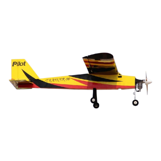
- Page 1 Trainer Assembly Trainer Assembly Manual www.pilot-rc.com il t -Pilot Trainer-...
- Page 2 -Pilot Trainer-...
- Page 3 -Pilot Trainer-...
- Page 4 1-) Locate both Plywood wing 2-) Insert both wing joiners inside joiners (Large and small one) one wing panel. 3-) Slide the other wing panel 4-) Bring both wing panels over the plywood joiners. together and verify for proper fit. -Pilot Trainer-...
- Page 5 6-) Locate the 4 wing mounting the fuselage as shown. screws and washers from the enclosed hardware bag. 7-) Insert the 4 screws and washers in the pre-cut holes in the wing, securing them into the pre-installed “Blind-Nuts” inside the fuselage. -Pilot Trainer-...
- Page 6 10-) Measure from the other 11-) Once the stab is centered, side and equally space the stab draw a line on both side of the onto the fuselage. stab as shown, both top and b tt bottom of the stab. f th -Pilot Trainer-...
- Page 7 14-) Locate the control horns for 15-) Using a sanding bar, sand the hardware bag. the horn section (on both sides) th t ill b i that will be inserted into the t d i t th elevator for better glue adhesion. -Pilot Trainer-...
- Page 8 18-) Apply 30-minute epoxy to 19-) Before the epoxy cures, align both the stab and fuselage the stab by equally measuring sections and slide the stab into from each wing tips as reference. position. -Pilot Trainer-...
- Page 9 Tail group assembly -FIN POST- 21-) Cut and remove the covering 22-) Mix some 30-minute epoxy from the bottom of the fin post. and apply to both the fin and pp y fuselage inner sections. Secure with masking tape. -Pilot Trainer-...
- Page 10 21mm from the top of the stab. remove the covering and trial fit NOTE: The bend must be parallel NOTE: The bend must be parallel the steel wire into it the steel wire into it. to the rubber tail wheel. -Pilot Trainer-...
- Page 11 30- and cut/remove the covering. Plug minute epoxy. one servo to each pre-installed servo leads and secure with the supplied servo retainer clips. -Pilot Trainer-...
- Page 12 (short one) to the servo arm. 32-) Completed rudder pushrod 33-) Repeat the same process for installation shown here for the elevator servo. Use the reference. remaining long pushrod from the hardware bag hardware bag. -Pilot Trainer-...
- Page 13 37-) Like the rudder and elevator ailerons/flaps and bond a control ailerons/flaps and bond a control hinges repeat the same procedure hinges, repeat the same procedure horn into each slots using 30- for bonding both the flap and aileron minute epoxy. hinges. -Pilot Trainer-...
- Page 14 40-) All servo lead extensions 41-) Repeat the same procedure should pass through the pre-cut for the flap servos. holes in both wing panels as shown shown. -Pilot Trainer-...
- Page 15 Wraps” to make sure it will not should be installed using plastic move inside the fuselage move inside the fuselage. “tie-Wraps” to secure it in place tie-Wraps to secure it in place. Secure the removable hatch with two wood screws. -Pilot Trainer-...
- Page 16 Left sides) and 1 fuel dot. 47-) The fuel dot receptacle is fitted to the fuselage . You have to unscrew the fuel line plug to fill the fuel tank plug to fill the fuel tank. (Picture for reference only) -Pilot Trainer-...
- Page 17 Axel Collar 50-) Secure the main gear with 51-) Install one wheel axel on the supplied screws and washers each sides of the gear and from your hardware bag. insert one wheel collar over the axel as shown. -Pilot Trainer-...
- Page 18 54-) Using one Brass sleeve, 55-) Crimp the Brass sleeve pass the steel cable in a “loop against the steel cable and cut style” in order to make a knot t l ” i the remaining cable. into it. -Pilot Trainer-...
- Page 19 -Slide the steel nose gear through the Nylon support and the Nylon steering arm. Connect the steering arm to a servo inside the fuselage front section -Tighten the set-screw in the steering arm directly over the “flat” section of the steel nose gear. -Pilot Trainer-...
- Page 20 2-) Dry fit the two parts F51, one F51A, one Brass sleeve and one as shown. This part will be bonded latter inside the top Black tube. NOTE: Part F51A goes towards the front of the fuselage. section of the fuselage. -Pilot Trainer-...
- Page 21 5-) Bond the Brass sleeve into insert the two parts F51 in the both F51’s as shown. Remove remaining two slots. Then, push some small material in front of in completely the Black tube. the first F51 to expose the wood. -Pilot Trainer-...
- Page 22 F51, over the removed line with the fuselage slot, allowing covering. the servo arm to protrude outside of the fuselage. -Open position- -Closed position- -Pilot Trainer-...
- Page 23 N t f Note from Pilot RC: Pil t RC -Included are Laser-Cut plywood parts. These parts are provided to allow you to repair your Trainer in case of a mishap. -If you need additional parts, please contact Pilot RC directly.
Need help?
Do you have a question about the Trainer and is the answer not in the manual?
Questions and answers