Advertisement
Quick Links
Advertisement

Related Manuals for Pilot Communications Bergfalke II-55 Glider


Summary of Contents for Pilot Communications Bergfalke II-55 Glider
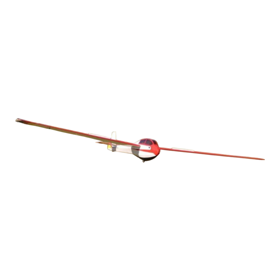
- Page 1 Bergfalke II-55 Glider 5,5meter/217 wing span -Instruction manual-...
- Page 2 4-) Trial fit both horns with the 3-) Sand one side only of the horn retainer and adjust as horn retainer as shown. The required for perfect matting. sanded side will face on the elevator surface. -Bergfalke II-55 Glider-...
- Page 3 8-) Align both horns so that the horn assembly, where it will fit holes in both of them are into the elevator. parallel to each other. Let the epoxy cure. Repeat the same process for the Right elevator. -Bergfalke II-55 Glider-...
- Page 4 11-) Also sand the two rudder 12-) Slide one retainer as horn retainers (Left/Right) and shown to keep the assembly in clean with alcohol. line. The sanded surface must face inwards of both horns. -Bergfalke II-55 Glider-...
- Page 5 14-) Position the second horn epoxy to the horn assembly retainer with epoxy and adjust and insert into position. both horns so that they properly match. 15-) Repeat the horn assembly 16-) Locate the wheel & proceedure for both ailerons. accessories. -Bergfalke II-55 Glider-...
- Page 6 19-) On the top and bottom (front 20-) Do the same on the front of section) of the stab, locate the the stab fuselage saddle section two small holes. Remove the to expose the pre-installed blind- covering to expose the holes. nuts. -Bergfalke II-55 Glider-...
- Page 7 40mm screws and washers. Once through all of the hinges as positioned, glue the stab to the shown. fuselage, after final assembly only. -Bergfalke II-55 Glider-...
- Page 8 27-) Then, cut the steel wire 28-) On the rear Left side of the flush with the wheel collar. fuselage, in front of the stab saddle, open the elevator servo cavity by cutting the covering film. -Bergfalke II-55 Glider-...
- Page 9 NOTE: The front of the servo Inside the cockpit section, pull must go towards the front of on the other end of the Red the fuselage. string and pull in the extension lead. -Bergfalke II-55 Glider-...
- Page 10 Repeat cables on both sides of the the process for the Right fuselage. Look at the picture elevator servo. carefully for reference. Use a knife to cut and remove the covering. -Bergfalke II-55 Glider-...
- Page 11 39-) Use one of your servo 40-) Secure your arm arms and the supplied underneath the composite arm, composite rudder arm. making sure that both center holes are in line. -Bergfalke II-55 Glider-...
- Page 12 Secure the rudder servo arm C.A. assembly. Locate the pull-pull cables. Two of the ball links are not crimped on the cables. Remove them and screw them to the rudder arm as shown. -Bergfalke II-55 Glider-...
- Page 13 Brass shrinkable tube over the Brass retainers. NOTE: Crosse the crimps. Using a heat-gun, cables in an X fashion inside shrink the tube as shown. the fuselage. This will provide a thither pull-pull cable set-up. -Bergfalke II-55 Glider-...
- Page 14 . Install a Attach it to this servo. This servo in that cavity. pushrod will exit from the nose and will secure the towing cable to your glider (see next two pictures) A-) Closed B-) Open position. position. -Bergfalke II-55 Glider-...
- Page 15 Brass spacer as shown. You will spacer using one of the M3 need to shave the spacers for screws. proper fitting between the spoiler hinges. Then, secure the screw with an M3 nut (Do not over thigh the nut) -Bergfalke II-55 Glider-...
- Page 16 Using your finger, locate the three slots in the wing, in front of the spoilers. Once located, cut the covering to allow the spoilers to move upwards. A-) Spoilers down B-) Spoilers up position. position. -Bergfalke II-55 Glider-...
- Page 17 60-) Slide the pushrod from the long pushrod and put one ball bottom of the wing into the link at each ends. front servo cavity. Attach one end of the pushrod to the center spoiler rib as shown. -Bergfalke II-55 Glider-...
- Page 18 A-) Spoilers DOWN. B-) Spoilers UP. 61-) Secure the top spoiler servo 62-) Secure the bottom spoiler cover at each corners with the cover at each corners and center supplied wood screws. with the supplied wood screws. -Bergfalke II-55 Glider-...
- Page 19 W39L covers for reference. 65-) The picture is self- 66-) Make sure that there is no explanatory. Secure the cover play or friction at all pivot with the supplied wood screws. points in the linkages. -Bergfalke II-55 Glider-...
- Page 20 -The C.G is located at ¾ /19mm behind the leading edge of both wing panels, near the fuselage section. -It is normal to add up to 4 pounds/1.8 kilo in the nose section to balance this glider. -Bergfalke II-55 Glider-...
Need help?
Do you have a question about the Bergfalke II-55 Glider and is the answer not in the manual?
Questions and answers