Table of Contents
Advertisement
Quick Links
Advertisement
Table of Contents

Related Manuals for Pilot Communications Decathlon 180


Summary of Contents for Pilot Communications Decathlon 180
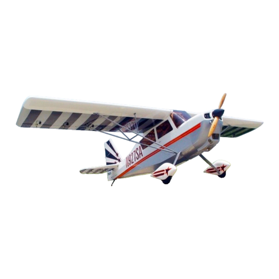
- Page 1 Decathlon 180” USER MANUAL WINGSPAN: 4580mm LENGTH: 3170mm...
- Page 2 Introduction Thank you for purchasing our Deacthlon plane. we strive to achieve a good quality quick build ARF aircraft . It requires the least amount of assembly of any ARF kit to obtain the maximum performance. Both the design and manufacturing have been undertaken to the highest standards, using best quality hardware, covering, wood &...
- Page 3 Rudder Assembly Rudder Horn Slice covering over factory installed slots. Press control horn into position. Trace around the locking plate with a knife and remove the covering. Scuff the middle of horns with a piece of sand paper for good glue bond.
- Page 4 Rudder Assembly Apply the 30 minutes epoxy inside the pre-cut slot, and coat the horn with epoxy as shown. Slide the horn into slots with locking mount plates. Wipe away excess glue with rubbing alcohol. Make sure the horn is perpendicular to the rudder.
- Page 5 Tail Wheel Assembly Draw a line here Draw a center line with a fine line marker as shown. Locate and drill holes in the tail wheel mounting block. Install the blind nuts through the opening in the rear of the fuselage. Mount the tail wheel assembly using blue Loctite on the threads screws.
- Page 6 Tail Wheel Assembly Install the hatch over the opening in the rear of fuse with 3 screws in accordance with the pre-drilled holes Drill a 1mm hole in the bottom of the rudder and mount steering spring with a wood screw as shown. Cut off excess wire from the spring. Ensure the spring is under slight tension.
- Page 7 Landing Gear Assembly Straight edge to front NOTE: The main landing mounting direction. Taper to rear...
- Page 8 Landing Gear Assembly Install the landing gear with the bolts and locking nuts. Do not over tighten the hardware. Install the landing gear axles with lock nut. Tighten the lock nut against the landing gear strut making sure the flat sides of the axle bolt vertical with ground.
- Page 9 Wheel Pants Assembly Level the fuselage and place the wheel pants over the wheels. The cut out in the wheel pant is cut to fit the hex nut on the axle. Check for proper clearance over the wheels and that wheel pants are level with the fuselage.
- Page 10 Servo Arm/Horn Assembly Servo Arm Installation Minimum servo specs:180 in. Oz / Metal Gear / Digital Use a few drops of CA to hold arm in place for drilling. Use a drop of CA glue on each nuts. Turn on your transmitter and make sure servos are centered before putting on servo arms.
- Page 11 Servo Arm/Horn Assembly Slice covering over factory installed slots. Press control horn into position. Trace around the locking plate with a knife and remove the covering. Scuff the horns with a piece of sand paper for good glue bond. Wipe off sanding dust prior to gluing.
- Page 12 Aileron/Flaps Servo Installation Add a servo extension to each aileron servo. Install connector safety clip to as shown to connection. Locate servo cut outs and remove the covering with a knife. Tape the servo lead securely to the pull-string Pull the extension lead through to the root of the wing. Use a 1mm drill bit to drill for the servo mounting screws.
- Page 13 Aileron/Flaps Servo Installation Install the servo arm facing outboard toward the wing tip. Adjust pushrod length so the servo arm is at 90 degrees and aileron panel in neutral position. Rudder servo installation...
-
Page 14: Elevator Servo Installation
Elevator Servo Installation Connect the servo extension to the servo and install safety clip. Snake the elevator servo leads into the fuselage using the factory installed pull string. (same process as ailerons) Use 1mm bit to drill the mounting holes. Install the servos with the out put shaft facing forward. - Page 15 Elevator Servo Installation Install the stab with mounting bolts and washers. Apply Loctite to threads before installation. Install the servo arm facing down. Adjust pushrod length so the elevator is neutral and the servo horn is at 90 degrees. Repeat steps for the other elevator servo.
- Page 16 Rudder Servo Arm Installation Hold with tape or a few drops of CA to the edges. Drop CA glue on nuts Turn on your transmitter and make sure servos are centered before installing the rudder servo arm. Drill holes with a 2mm bit for hardware. Mount the screws and nuts.
- Page 17 Rudder Servo Installation (1) The rudder cables and couplers come factory installed as shown. Drill 1mm holes and mount the rudder servo with the output shaft facing forward. Install the rudder servo arm with cable attach points aft. Tape the rudder to the vertical fin in the neutral position to help with the rigging.
-
Page 18: Rudder Servo Installation
Rudder Servo Installation (1) The flat surface of the ball link gets screwed against the servo arm. Install ball link to rudder control horn temporarily. Prior to connecting rudder cable to the ball link, slide a section of heat shrink tubing and copper tubing. - Page 19 Rudder Servo Installation (2) The process for the rudder servo installation is the same process as for the ailerons.
- Page 20 Engine Installation Using a template, locate, drill, and install the engine centered to the firewall. Fit the firewall with the attached engine into the motor box (without glue). Install the engine cowl over the engine. Install the spinner bulkhead onto the engine and center the spinner bulkhead with the cowl.
-
Page 21: Engine Installation
Engine Installation Note: Use Blue Loctite on final installation of engine mounting screws. -
Page 22: Throttle Servo Installation
Throttle Servo Installation Drop glue on the nut Install the throttle servo in the included mounting tray. Mount the tray in the engine box behind the fire wall. Make pushrod path is in a straight line for a precise throttle linkage connection. Epoxy and screw the tray in place. -
Page 23: Ignition Module Installation
Ignition Module Installation Attach foam rubber to the bottom of ignition with double sided tape and install spiral wrap cover to ignition lead. Stick the ignition to the outside of the engine box with double sided tape. Allow room for spark plug leads and wire connections. Drill holes in motor box for zip ties and secure module with ties. - Page 24 Engine Box Hatch Epoxy the hatch in place and install self-tapping screws Fuel Tank Installation To engine To fueling dot To atmosphere...
- Page 25 Fuel Tank Installation Mount the fuel tank with Velcro straps. There is a factory laser cut hole for the fueling dot aft of the engine cowl on the left hand side of the fuselage. Secure all fuel lines connections with zip ties.
-
Page 26: Cowl Installation
Cowl Installation Note: Avoid sharp corners to prevent stress cracking from vibration. Note: An extended Allen wrench is needed to reach the hardware to remove and install the cowl Use a Dremel cutting tool to rough cut the cowl for clearance for the exhaust system and for additional cooling. -
Page 27: Switch Installation
Switch Installation Factory installed laser cut switch mounting holes are located under the covering on either side of the fuselage for your convenience. Opening the cabin door exposes two additional pre cut switch locations in the servo mounting plate. Finish the mounting the switch with screws and nuts. - Page 28 Wing Assembly Wing brackets Install the brackets at mounting locations under side of wing. Use Loctite on threads. Short side Lift strut components...
- Page 29 Wing Assembly Layout, identify, and assemble lift strut components. Do not fully tighten hardware at this time.
- Page 30 Wing Assembly Use the included spacers and mount the lift struts to the wing. Thin spacers are for the out board brackets and thick spacers for the inboard brackets. Leave hardware lose. Install wings on fuselage and make sure every thing is aligned. Tighten all hardware.
-
Page 31: Elevator Assembly
Elevator Assembly Brackets Install the aluminum brackets onto the tail for the wire bracing. There are a total of seven brackets for the tail assembly. There are four identical brackets that are for the horizontal stabilizer, two with steeper bands that are for the vertical stabilizer, and a double sided bracket that mounts on the aft screw of the tail wheel bracket under the fuselage. - Page 32 Elevator Assembly Note: make sure cable tensions are balanced to prevent warping.
- Page 33 LED Lights Assembly (Optional) Pilot-RC LED lighting kit (optional)
-
Page 34: Centre Of Gravity
Centre of Gravity The center of gravity is near to the wing tube .For more plane please refer to the CG list. Avoid adding weight to your Decathlon for CG purposes. Position the batteries where required in order to correctly balance your model. Mount batteries on a bed of foam and secure with Nylon ties or Velcro straps. - Page 35 Centre of Gravity List of PilotRC CG(from CG(from the LE of the LE of Plane Note Plane Note the root of the root of the wing) the wing) YAK54-73 156mm 540-V3-67 96.5mm YAK54-87 183mm 540-V3-78 141mm YAK54-107 255mm 540-V3-78...
-
Page 36: Flight Preparation
Flight Preparation ■ Make sure you have the right model programmed into your transmitter ■ Check the direction of each surface not and also right before you take off . ■ Remember nothing wrong on the ground ever improves in the air ■... - Page 37 Zhongshan Pilot Model Aircraft Product Ltd Address: No.34, Chengnan Er Road, Zhongshan city, 528455, Guangdong Province, China Web: www.pilot-rc.com Email: pilot-rc@139.com, info@pilot-rc.com Tel: +86-760-88781293 FAX: +86-760-88780293...
Need help?
Do you have a question about the Decathlon 180 and is the answer not in the manual?
Questions and answers