
Subscribe to Our Youtube Channel
Related Manuals for Pilot Communications COLUMBIA 400


Summary of Contents for Pilot Communications COLUMBIA 400
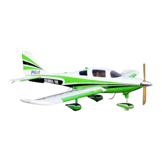
- Page 1 Assembly Manual For Columbia 400 bi 400 Wingspan: 88 in Wingarea: 1479.8 sp in Length: 78.8 in Engine: 50CC www.pilot www.pilot- - rc.com il il rc.com...
-
Page 2: Introduction
INTRODUCTION Thank you for purchasing Thank you for purchasing our Columbia 400. we strive to achieve the real Quick Builded and ARF aircraf . It just requires the least amout of assembly of any kit amout of assembly of any kit that almost finished in factory.To obtain the perfect... -
Page 3: Warranty
WARRANTY WARRANTY ■ ■ All Pilot-RC products are guaranteed against All Pilot-RC products are guaranteed against defects for 30 days of receiving your airplane. This warranty is limited to construction or productions defects in both material and workmanship , doesn't cover any component parts damaged by use or modification . -
Page 4: Attention
ATTENTION ATTENTION You should not regard this plane as toy! You should not regard this plane as toy! ■ ■ ■ To ensure safety,please read the instruction manual thoroughly before assembly . ■ Building and operating model plane require diligent practicing and correct guidance. Any neglect,carelessness and missing experience can cause serious bodily harm and property damage. -
Page 5: Table Of Contents
INDEX Introduction ………………….………..….…….…. Warranty …………………….……..….…..……. Attention …………….…………..….……..……. Fuselage Unit Landing Gear Assembly Front landing Gear Installation ………….…..……. Rear landing Gear Installation …………..….……… Servo Unit Servo Unit Wing Servo Assembly ………….….………. Rudder Assembly ………….……….….. Rudder Servo Assembly ….…….…..…….. Elevator Servo Assembly ………….……………. -
Page 6: Landing Gear Assembly
Landing Gear Assembly Front Landing Gear Installation Front Landing Gear Installation... - Page 7 Landing Gear Assembly 1, there are 6 holes in the bottom of 3. Inside view of mounting front the engine box which are for the landing gear. front landing gear. 4 Outside view of mounting front 2. Mount the front landing gear to landing gear.
- Page 8 Landing Gear Assembly 5. Install the servo for front landing gear. Put the servo to the servo bay 7. Adjust the rod length to make the which is on the back of the firewall. front wheel in the middle place. 8.
- Page 9 Landing Gear Assembly 9. Take off this bolt. 10. Take off the bottom part of the 11. Install the tire into the front landing gear . landing gear with the circlips outside.
- Page 10 Landing Gear Assembly Install the front wheel pants: Note: the front wheel pants are 2. Put the pants into the front different shape from the rear landing gear . wheel pants. 3. Screw two side bolt to fit the wheel 1.
- Page 11 Landing Gear Assembly Install the front landing gear covering: Note: The front landing gear covering only install after you install the cowl. 1. Cut the hole on the bottom of the 3. Screw two bolts in front of the cowl to fit the front landing gear. landing gear covering.
- Page 12 Finished front Landing Gear covering Finished front Landing Gear covering...
-
Page 13: Rear Landing Gear Installation
Landing Gear Assembly Rear Landing Gear Installation Rear Landing Gear Installation... - Page 14 Landing Gear Assembly 1, Find the slot for the landing gear on the rear of the wing. Cut the 3, Install the aluminum connecting covering. Put the landing gear into angle between two side landing gear the slot. as shown 2.
- Page 15 Landing Gear Assembly 5. Make the flat sides of the axle bolt 7. Drill the holes for the mounting vertical with grond .Then tighten the bolts and install the blind nuts. lock nut against the landing gear strut 6. Install the collars and wheel in 8.
-
Page 16: Wing Servo Assembly
Wing Servo Assembly Wing Servo Assembly Servo Arm Installation 2. Ensure the servo arm is 90 Minimum Request Servo: degrees with servo as shown. Then 15 kg.cm / Metal Gear mark and drill holes with 2mm bit Pre fasten the arm with drops of fast cured gule on edge 1. -
Page 17: Aileron Control Horns
Wing Servo Assembly 2. Trace around the locking plate Aileron Control Horns with kinfe and cut off the cover below.Then the pre-cut slots appear 3. Scuff the horns with a piece of 1. Tear off the cover on the horns sand paper for good glue bond.Then and locking plates clean up the surface... - Page 18 Wing Servo Assembly 4. Apply the 30 minutes epoxy Servo Installation inside the pre-cut slot for horn ,and coat the horn with epoxy as shown 5. Slide the horn into slot slightly 1. Cut out the cover for servo location and Mount the locking plate in carefully as shown place Wipe away excess epoxy...
- Page 19 Wing Servo Assembly 2 Lock the connector with the 2. Lock the connector with the 4. Then put the extention lead provided safety clip against vibration through the root of wing and loosened tension as shown 3. Cut out the cover for servo 5.
- Page 20 Wing Servo Assembly 6 Glue two piece of wood to the 6. Glue two piece of wood to the servo mounting plate as shown Note: Be sure to glue it strong enough. 7. Use 1mm bit to drill the mounting 8.
- Page 21 Wing Servo Assembly 6 Install the servo arms facing 6. Install the servo arms facing 7 Repeat all the step above for the 7. Repeat all the step above for the toward the wing edge and adjust flap . pushrod in proper length to keep the aileron panel on the neutral position...
-
Page 22: Rudder Control Horn
Rudder Assemby Rudder Assemby y 2. Trace around the locking plate Rudder Control Horn with kinfe and cut off the cover below.Then the pre-cut slots appear 3. Scuff the middle of horns with a 1. Tear off the cover on the horns piece of sand paper for good glue and locking plates bond Then clean up the surface... -
Page 23: Rudder Assembly
Rudder Assembly 4. Apply the 30 minutes epoxy Make sure the horn line up with inside the pre-cut slot, and coat the ground and align the both side horn with epoxy as shown before epoxy has cured` 5. Slid the horn into slot slightly ,mount the locking plates in place.Wipe away excess glue with rubbing alcohol... -
Page 24: Rudder Servo Assembly
Rudder Servo Assembly Servo Tray Installation Servo Tray Installation 2. Drill holes with 2mm bit Minimum Request Servo: 15 kg.cm / Metal Gear 1. Turn on your radio device 3. Mounting screws and nuts according the Wing Servo Installation.Keep the tray holes on center and the arm aligned with d i h A drop of fast... - Page 25 Rudder Servo Assembly Servo Installation Servo Installation 3 Attach the pre installed boll link 3. Attach the pre-installed boll link to the rudder horn and not tighten the locking nut 1. Mount servo with mounting screws and face the brand toward Turn on your radio to keep the the rudder.Drill holes with 1mm bit servo neutral.
- Page 26 Rudder Servo Assembly 7. Thread the coupler in 2 – 4 mm 5. Crimp them in place with crimping (according the bolt holes center). pliers Ensure the same length of cables and tension 2-4mm 8 Shrink the heat shrinking tube on 8.
- Page 27 Rudder Servo Assembly 9. Remove the ball links from rudder horn and install the servo arm ball links with bolts and nuts Turn off the radio now. Reinstall the ball link (Don’t pull strongly to hurt the rudder or back to step 7 for readjustment )you can find a helper and do that at certain deflection with and do that at certain deflection with...
-
Page 28: Elevator Servo Assembly
Elevator Servo Assembly Servo Arm Installation 2. Ensure the servo arm is 90 degrees with servo as shown. Then mark and drill holes with 2mm bit Minimum Request Servo: 180 in.zo / Metal Gear / Digital Pre fasten the arm with drops of fast cured gule on edge 1. - Page 29 Elevator Servo Assembly 2. Trace around the locking plate Elevator Control Horns with kinfe and cut off the cover below.Then the pre-cut slots appear 1. Tear off the cover on the horns 3. Scuff the horns with a piece of and locking plates sand paper for good glue bond.Then clean up the surface...
- Page 30 Elevator Servo Assembly 4 Apply the 30 minutes epoxy 4. Apply the 30 minutes epoxy Servo Installation inside the pre-cut slots, and coat the horn with epoxy as shown 5. Slide the horns into slots slightly and Mount the locking plate in 1.
- Page 31 Elevator Servo Assembly 4. Lock the connector with the 2. Install servos with mounting 2. Install servos with mounting provided safety clip against vibration screws. Face the brand toward the and loosened tension as shown rear of fuse. 3. Install the servo arm with mounting screw and make it vertical with 5.
- Page 32 Elevator Servo Assembly 6 Install the stab with mounting 6. Install the stab with mounting 7 Repeat all the step above for the 7. Repeat all the step above for the bolts and washers other stabilizer...
-
Page 33: Engine Unit
Engine Uint Note: The cowl is already pre-build for right thrust and down thrust The for right thrust and down thrust. The Firewall Assembly ll A center of the engine axle will be in Note: The 2 degree RIGHT thrust the exact center of the cowl. - Page 34 Firewall Assembly 4 Epoxy the firewall with 30 minutes 4. Epoxy the firewall with 30 minutes 2. Drill the firewall according pre-set epoxy and use the mounting screws laser holes for DA-100. Otherwise and locker nut to fasten it immediately measure your engine’s mounting as shown location.
-
Page 35: Engine Assembly
Engine Assembly Engine Installation Throttle servo Installation Not Include Remember: Use Bue Loctite on all 1. Install the engine throttle arm engine mounting screws witn a little Blue Loctite... - Page 36 Throttle servo Installation 2 Measure and cut the extra wire 2. Measure and cut the extra wire 4. Epoxy the mounting tray in place Then bend to a sharp of “z” as shown and secure with self-tapping screws Mount the throttle pushrod to engine. A drop of fast cured gule 3.
-
Page 37: Ignition Module
Ignition Module 2 Position the ignition outside the 2. Position the ignition outside the Ignition Module engine box to allow the spark plug leads to connect the engine without excess tension .Drill for Nylon tie 1. Tape foam rubber on bottom of 3. -
Page 38: Hatch And Fuel Tank
Hatch And Fule Tank Fule Tank and Dot Fule Tank and Dot Engine Box Hatch H t h Fule Fill Line Fule line Epoxy the hatch in place and secure Fule tank and fule dot have been with self-tapping screws installed.Just tighten the velcro ties... -
Page 39: Final Assembly Unit Cowl Assembly
Crowl Assembly 2 Use a fiber cutting tool to rough 2. Use a fiber cutting tool to rough Crowl Assembly cut the cowl and finish with a round sander 1. Make a pattern of the exhaust 3. Ensue all the corner are rounded with a paper to hold its shape. -
Page 40: Canister Assembly
Canister Assembly Canister Assembly 3. Install the headers. 1. Put the canister to the mounting. 2. Glue the mounting to the canister room. - Page 41 Canister Assembly Canister Assembly 4. Cut the covering on the canister room cover. This is very important because it will cool the engine.
-
Page 42: Light System Assembly
Light system Assembly 1, All light already pre-install in the factory. You only need to 1, All light already pre install in the factory. You only need to connect the wire to the flashing controller. - Page 43 Light system Assembly 2, There is a wood cover near the light on the wing front edge. You can cut the Ultracote (Oracover). Open it and check the light if the light has problem.
-
Page 44: Handrail Assembly
Accessories Assembly Handrail Assembly 3. Cut the covering on the hole. 1. The handrail is on two side of Put some glue into the hole. Then the fuselage. Near the back put the handrail into the hole. window on the fuselage as shown: 2. -
Page 45: Canopy Lock Assembly
Accessories Assembly Canopy Lock Assembly Footplate Assembly Drill a 1mm diameter hole. Then screw the bolt to fix the canopy screw the bolt to fix the canopy lock. -
Page 46: Footplate Assembly
Accessories Assembly Footplate Assembly 3. Put the footstep into the hole. 1. Find the hole for footstep. Cut Screw the bolt into the blind nut. the covering. 2. There is a blind nut for the footstep inside the fuselage footstep inside the fuselage. -
Page 47: Accessories Assembly
Accessories Assembly Wing and aileron Wing and aileron Antenna and other antenna Assembly accessories Assembly 1.Find the hole on the wing and aileron as shown. 2. Put some glue on the black tip of the antennas. Then insert the antennas into the hole antennas into the hole. - Page 48 Accessories Assembly Vertical tail and rudder Vertical tail and rudder St bili Stabilizer and elevator antenna Assembly antenna Assembly 1.Find the hole on the stabilizer 1.Find the hole on Vertical tail and and elevator as shown. rudder as shown. 2. Put some glue on the black tip of 2.
- Page 49 Accessories Assembly Fuselage bottom Fuselage bottom antenna Assembly 2.Glue the accessories on the 1.Find the place on the bottom of bottom of the fuselage. the fuselage for antenna as shown. Cut the covering. Cut the covering.
- Page 50 Accessories Assembly Fuselage top Fuselage top accessories Assembly 2.Glue the accessories on the top 1.Find the place on the bottom of of the fuselage. the fuselage for antenna as shown. Cut the covering. Cut the covering.
-
Page 51: Cg And Control Throws
CG And Control Throws Center Of Gravity The First Flight set up The center of gravity is marked inside the fuselage. Near to the Throttle: Adjust idle –full wing tube as shown. Elevator: 40 Degrees on High rate 12 Degrees on Low rate Aileron: 30 Degrees on High rate 12 Degrees on Low rate... -
Page 52: Fli H P Flight Preperation I
Flight Preperation Make sure you have the right model programmed into your Make sure you have the right model programmed into your ■ ■ transmitter Check the direction of each surface not and also right before ■ you take off . Remember nothing wrong on the ground ever improves in ■... - Page 53 Pilot RC Control Horn Installation (50cc and larger have dual control horns & 30cc Aircraft have a single control horn) • Rubber/Latex Gloves. • Epoxy (30 Minute or Stronger) • Epoxy Mixing Cups • Epoxy Mixing Sticks (Any mixing stick that will fit into the slot) •...
- Page 54 Then you will need to test fit your parts together before gluing in place. Please note that sometimes the slots need to be cleaned out a little bit and can be done with a dremel and a small drill bit or an x-acto knife. Force your epoxy into the slots.
- Page 55 Install your horns. Make sure to clean off any epoxy that comes out from under the plate with a paper towel and alcohol.
- Page 56 Pilot RC Wing & Elevator Servo Installation You will need: • Hobby Iron • X-Acto Knife • Thin CA “Super Glue” • Drill and Drill Bit First find the servo mounting hole and iron around to assure that the covering is stuck to the surrounding wood.
- Page 57 Then press and iron excess covering down into the servo slot. Now you can pre fit the servo. Make sure your grommets are installed and drill the holes for the servo screws.
- Page 58 Now apply a small amount of the CA to the already drilled servo screw holes and if need- ed run your extension wire through. (Don’t forget the safety clip!!) Now you can install the servo with your choice of screws and attach the linkage. Final adjustment of turnbuckles and it ready for servo adjustment.
- Page 59 Pilot RC Optional Rudder Installation for 50-150cc Aircraft Shorten the rudder wire so that it will not pierce the covering at the top of the rudder and leave about 3/4” hanging out the bottom. Bend the bottom at a 90 degree angle, and then trace around the wire (See Photos).
- Page 60 The Tail wheel bracket will lock it in to place. Make sure it overhangs the slot when you install the TW bracket.
-
Page 61: Center Of Gravity
CG can be moved around to fit your personal taste. DECATHLON 107” 133mm/5.2inch DECATHLON 122’’ 145 mm/5.7inch DECATHLON 150’’ 182 mm/7.2inch Columbia 400 128’’ 136mm/5.35inch DECATHLON 180’’ 217 mm/8.5inch Columbia 400 150’’ 141mm/5.6inch YAKM55 73” 165mm/6.5inch Edge-540 73’’...
Need help?
Do you have a question about the COLUMBIA 400 and is the answer not in the manual?
Questions and answers