Table of Contents
Advertisement
Quick Links
Advertisement
Table of Contents

Related Manuals for Pilot Communications Pitts Challenger


Summary of Contents for Pilot Communications Pitts Challenger
- Page 1 Pitts Challenger – 87″ – 2.20m (100cc) MANUAL...
-
Page 2: Your Model
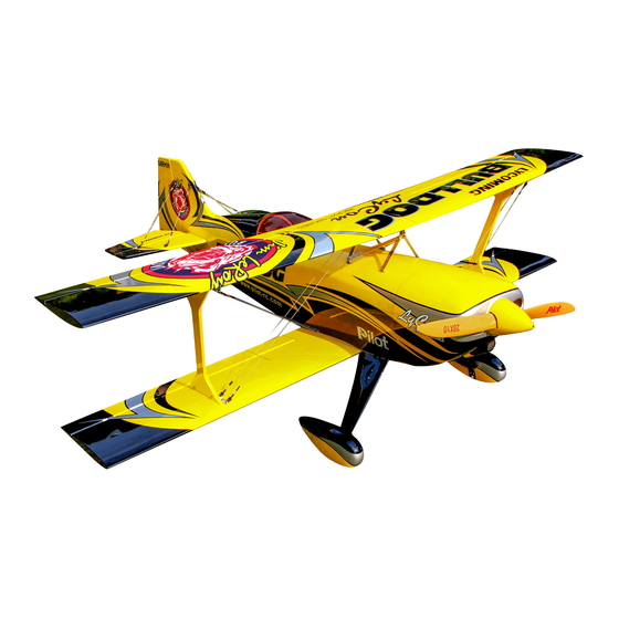
Please read through these instructions before you start building or flying to assure a successful experience, and welcome to Team Pilot-Rc! YOUR MODEL: Model: Pitts Challenger Wingspan: 87 ″ (2,200mm) Length: 84″ (2,120mm) Wing area: 2,265 “²... -
Page 3: Required Hardware
REQUIRED HARDWARE Motor: 100-120cc Servos: 7-8 high torque plus throttle // Uses x1 per aileron (total x4), x1 per elevator and x1 or x2 on rudder... - Page 4 Required extension wire lengths: x2 for bottom wing aileron servo: 60cm x2 for top wing aileron servo: 87cm (installed in bottom wing) + 52cm (installed in wing struts) x2 for elevator servo: 95cm x1 for throttle servo Also requires all the usual accessories such as transmitter, receiver, batteries, powerbox and possibly other small accessories…...
- Page 5 warranty is limited to construction or production defects in both material and workmanship, and does not cover any parts damaged due to misuse or modification. Should you wish to return this airplane for any reason, all shipping costs are the responsibility of customer.
- Page 6 Pilot-RC reserves the right to update the model, instructions and limited warranty without notice. If you have any problems and questions, please contact Pilot-RC: Web: www.Pilot-Rc.com Email: pilot-rc@139.com, info@pilot-rc.com Phone: +86 760 88781293 FAX: +86 760 88780293 Address: No34, Chengnan Er Road, Zhongshan City, 528455, Guangdong, Province, China. 3- Assembly Please note that pictures are for reference only.
- Page 12 TAIL WHEEL AND ELEVATOR GUIDE WIRES INSTALLATION: With the model still upside down, draw the centre line of the section where the carbon tail wheel unit will be located, and then mark the location where you need to drill the holes for the bolts that will hold the tail wheel in place.
- Page 16 INSTALLING THE CONTROL HORN ON THE ELEVATOR: It is very important to sand horn to assure a strong bond once glued to the model. Locate and cut the covering where the horns will be glued Glue them to the surface using epoxy glue Excess epoxy glue can be removed with acetone...
- Page 20 INSTALLING THE CONTROL HORN ON THE RUDDER: It is very important to sand horn to assure a strong bond once glued to the model. Locate and cut the covering where the horns will be glued Glue them to the surface using epoxy glue Excess epoxy glue can be removed with acetone...
- Page 27 INSTALLING THE CONTROL HORN ON THE AILERONS: It is very important to sand horn to assure a strong bond once glued to the model. Locate and cut the covering where the horns will be glued Glue them to the surface using epoxy glue Excess epoxy glue can be removed with acetone...
-
Page 31: Aileron Servo Installation
AILERON SERVO INSTALLATION: Locate and cut the covering where the servo will be installed. We recommend cutting only the diameter of the main part of the servo. Allow the servo to sit on top of some Oracover, thus trapping and securing the Oracover in place. - Page 32 the pushrods provided.
-
Page 36: Rudder Servo Installation
RUDDER SERVO INSTALLATION: Screw the rudder servo to the allocated tray inside the fuselage Centre the servo with your transmitter and attach the double servo arm Attach the provided pull pull wires to the rudder control horns and thread the pull pull wire carefully through the fuselage slots all the way back to the actual rudder servo. -
Page 42: Elevator Servo Installation
ELEVATOR SERVO INSTALLATION: Locate and cut the covering where the servo will be installed, at the rear of the fuselage, just under the elevator. Attach your required extension lead to the servo, allowing sufficient length for the lead to reach your receiver or Powerbox without needing further extensions. -
Page 46: Motor Installation
MOTOR INSTALLATION: The Pitts is provided with the firewall pre-mounted at the factory, laser marked where the centre-line is, ready for you to simply square your engine to it. The engine box come with the appropriate engine incidences applied, so all you need to do is make sure that this any standoffs are all the same size to assure a correct engine incidence. -
Page 53: Throttle Servo
THROTTLE SERVO: For the installation of the throttle servo, simply screw the servo to the provided servo mount, and then screw and glue this in its final location where required for your particular engine. Use the included pushrod to connect to your engine, making sure that of a smooth and bind free movement. -
Page 57: Cowling Installation
COWLING INSTALLATION: The cowling is installed with a single pre-installed bolt on the top half, from the inside of the fuselage going forwards, and two additional bolts going through the cowling from the bottom. With the cowl off, turn the model over, and place some small strips of masking tape in line with the two bolt holes. - Page 59 INSTALLATION OF ANCILLARY COMPONENTS: Check the correct location of your chosen battery and ancillary components depending on your CG. Install your receiver with double sided tape or velcro, making sure that all servo leads can be easily connected without being too tight, and that the receiver is securely fixed in place. For specific tips on receiver and antenna location, please consult your receivers manual.
- Page 61 Note that the two laser cut holes are for the fuel and smoke tank vents...
- Page 62 WHEELS PANTS INSTALLATION: Slide the wheel pants over the wheels and axles, supporting the rear of the pants to line up with the ground and mark where to drill the two screw holes in the wheel pants. Remove the wheel pants and drill the holes for the appropriate holes. Before putting back on the plane, mount the bolt with the blind nut on the wheel pant and tighten until the nut sits flush with the wheel pant.
- Page 65 ELEVATOR GUIDE WIRES The guide wires are important as they add extra strength to both the elevators and the main wings. The elevator has guide wires both top and bottom. The bottom guide wires are fixed to the fuselage via the cross member installed previously (during the tail wheel step).
-
Page 70: Wing Struts
WING STRUTS The wing struts must be installed in the correct order and location in order to assure the correct wing angle and incidences. To make setup simple, inside the struts you will find laser engraved descriptions of where each side of the wing strut should be attached. - Page 73 WING GUIDE WIRES The wing guide wires are fitted with a quick release on one end, and are permanently fixed at the other. The support that we installed earlier under the landing gear is where the guide wires will be permanently attached, using the same crimping method described previously.
- Page 77 BALANCING THE CG OF AIRPLANE: The CG is marked on the central fuselage wing support. Thread wire through the indicated CG hole, then proceed to setup the model fully and then lift using said wire. The model should sit level when lifted. Personal CG preference can then be adjusted following the first flight.
-
Page 79: Field Setup
CONTROL THROW DEFLECTIONS AND SUGGESTED EXPO. General flying: Surface Deflection Expo Ailerons: 20º Elevators: 20º Rudder: 20º Full 3D acrobatics: Surface Deflection Expo Ailerons: 40º Elevators: 40º Rudder: 45º FIELD SETUP: Setup at the field can be done very quickly. The correct procedure for setup should be as follows:... - Page 81 0- The main “A” frame is permanently mounted to the fuselage 1- Insert the lower wing and secure to the fuselage, along with the servo connections 2- Secure the struts to the lower wing, along with the servo connection. This is done by simply sliding the quick release plate under the screws and tightening.
- Page 84 6- Secure the elevator tension wires as per picture below: All this can be done in just a few minutes:...
-
Page 85: Double Check
DOUBLE CHECK: Double check that all screws are installed, all components tightly secured, batteries and or fuel tank are full, all surfaces are working in the correct directions, balance is correct and range test passed before performing your maiden flight. WE WISH YOU A SUCCESFUL MAIDEN AND MANY HAPPY FLIGHTS WITH YOUR NEW MODEL.
Need help?
Do you have a question about the Pitts Challenger and is the answer not in the manual?
Questions and answers