Advertisement
Quick Links
Advertisement

Subscribe to Our Youtube Channel
Related Manuals for Pilot Communications Predator Sport Jet 90”


Summary of Contents for Pilot Communications Predator Sport Jet 90”
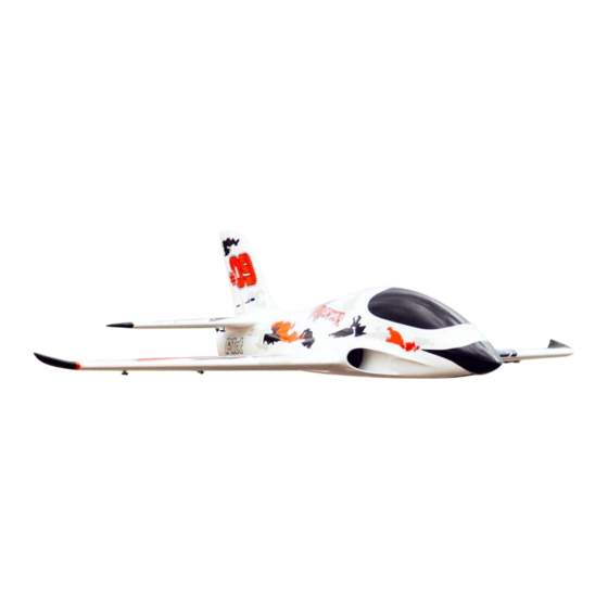
- Page 1 Predator Sport Jet 90” USER MANUAL...
- Page 2 ● Thank you for purchasing our Predator Sport Jet plane. we strive to achieve a good quality quick build ARF aircraft . It requires the least amount of assembly of any ARF kit to obtain the maximum performance. ● Both the design and manufacturing have been undertaken to the highest standards, using best quality hardware, covering, wood &...
- Page 3 Install kit contents: (Some contents like fuel tank etc… has already installed in fuselage) Aluminum tube: Accessories pack:...
- Page 4 Accessories pack includes: Socket head cap screws Counterstunk cross screws Cross round head with medium screws Tapping screws Hexagon screw in metric system(SHCS) Battery bandage Servo aluminum angle Metric Allen Wrench Push rot wrench Wring clamp Crowbar Crowbar Push rot: Oil nipple suit Extension cord: (Some of accessories like screw/cord etc…...
- Page 5 Landing gear module(optional): Landing gear(accessories included): Landing gear Pilot landing gear controller...
- Page 6 Servo module(optional): Servo: PY20AH Servo arm: Pilot Futaba aluminum alloy 0.8” Pilot Futaba aluminum alloy 1.2”...
- Page 8 Install the servo to the nose landing gear. Install the servo arm and the push rod. Adjust it to make sure the plane can go straight approx. You still can adjust by radio after install it.
- Page 9 Place the nose gear to the mounting and adjust it to the correct position, then mark the 4 mounting screws hole. Before you drilling the mounting screws hole , please make sure there is nothing to get stuck when it open and close.
- Page 10 Carefully arrange the nose gear retract wire lead and the steering wire as well ... After installation Thanks to the “Test” function of the Pilot- Thanks to the “Test” function of the Pilot- Rc controller unit, you can test the correct and free working of the system without the need for your transmitter or Install the nose retract gear to the...
- Page 12 1.Take out the aileron / flaps plating from the wing. With the wings upside down, position the gear in inside the wing on the mounting brackets and mark the location for the screws. Double check the positioning of your gear before drilling any holes.
- Page 13 3.Attach the included pushrods and ball links between the servo arm and the control horn. 4.Servo and servo arm installed...
- Page 14 6.Use a thin ply as a back plate and 5.Aileron servo / Flaps servo installed. installed the 4 in 1 connector , use 5 min epoxy to glue it from inside of the fuselage. 7.Just one connector for aileron/flaps/landing gear/brakes. One side of the connector can be screwed to the fuselage, while the other is left inside the wing, loose, for easy connections.
- Page 15 Rudder servo assembly 2.Insert the servo into the rudder, in its allocated slot, with the servo shaft closest to the rudder.
- Page 16 2. Find the 2 pcs M4 cap screws to 1.The rudder extension wire tighten it. It will hold the rudder connector. positio...
- Page 17 Elevators 2.Screw the servo in place, and then 1.Put in the servo to the precut slot install the servo arm on to the servo, in the elevator. making sure that this is centred 3: The other side of the servo connector glue at the side of the fuselage, just a drop of CA or 5 min epoxy to glue it.
- Page 18 1.You will find a top tube in the 2.You can use a fire proof tubing to keep top section of the fuselage! Servo the wire all isolate from heat. wire will slide in from the plastic tube all the way out from the tube. 3.To keep all the wire away from heat best…...
- Page 19 1.Next step is to get all servo wire 2.Predator jet come with high quality 2 through the tube under the fuel in1 Kevlar fuel tank. Kevlar smoke tank is tank...showed as the picture below. optional parts. 3.There are two fuel tank as seen in the picture, top one is the smoke tank and the bottom one is the main fuel tank with...
- Page 20 The 90” predator use PilotRC 2 in 1 Kevlar tank. It’s included 4600ml fuel tank, and 240ml UAT(and you can choose the 2000ml smoke tank as optional).
- Page 21 1.Please open the cap to check the fuel system is correct and clear the fuel tank (important) 3.Use the supply velcro strap to hold 2.The fuel system connected the fuel tank. Use double sticky tape to stick it.
- Page 22 2.Bottom view of the over flow vent, 1.The over flow vent installation you can connect a taxi tank if you wish...
- Page 23 2.Receiver / Dual BEC Pro installation 1.Electric landing gear / brake control and placement. box placement.
- Page 24 Battery install placement. On top of the nose gear.
- Page 25 The predator jet comes with CG measuring tools , very handy to check CG Please keep no fuel to check the CG. Click here for the video: https://www.facebook.co m/khaitang.wong/videos/ 1875569852454736/...
- Page 27 ■ Make sure you have the right model programmed into your transmitter ■ Check the direction of each surface not and also right before you take off . ■ Remember nothing wrong on the ground ever improves in the air ■...
Need help?
Do you have a question about the Predator Sport Jet 90” and is the answer not in the manual?
Questions and answers