
Related Manuals for Pilot Communications Sbach 342


Summary of Contents for Pilot Communications Sbach 342
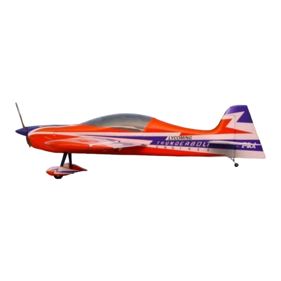
- Page 1 Assembly Manual For 53” electric sbach 342 53 electric sbach 342 Wingspan: 88 in Wingarea: 1479.8 sp in Length: 78.8 in Engine: 50CC www.pilot www.pilot- - rc.com il il rc.com...
-
Page 2: Introduction
INTRODUCTION Thank you for purchasing Thank you for purchasing our new 53” electric sbach 342. we strive to achieve the real Quick Builded and ARF aircraf . It just requires the least It just requires the least amout of assembly of any kit that almost finished in factory.To obtain the perfect performence,both the design... -
Page 3: Warranty
WARRANTY WARRANTY ■ ■ All Pilot-RC products are guaranteed against All Pilot-RC products are guaranteed against defects for 30 days of receiving your airplane. This warranty is limited to construction or productions defects in both material and workmanship , doesn't cover any component parts damaged by use or modification . -
Page 4: Attention
ATTENTION ATTENTION You should not regard this plane as toy! You should not regard this plane as toy! ■ ■ ■ To ensure safety,please read the instruction manual thoroughly before assembly . ■ Building and operating model plane require diligent practicing and correct guidance. Any neglect,carelessness and missing experience can cause serious bodily harm and property damage. - Page 5 Items needed for completion -masking tape -Thin and medium CA. -30 minute epoxy. -Electric drill with an assortment of small drill bits. -Small flat head and head screw drivers. -Standard and needle nose pliers. -4 sub micro metal geared servos. -Brushless Outrunner motor (you also can use other motor) Setup 1: Hacker A30-12XL Motor : http://www.hacker-motor-shop.com...
-
Page 6: Table Of Contents
INDEX Introduction ………………….………..….…….…. Warranty …………………….……..….…..……. Attention …………….…………..….……..……. Rudder Assembly ………….…………..….….. Landing Gear Assembly ………….…..……… Wing Servo Assembly ………….……………. Horizontal tail Assembly .………….…………. Elevator Servo Assembly ………….…………. Rudder Servo Assembly …………….…..……… Motor Assembly ………….….………..….……. Cowl Assembly …………………………...…..…… ……………………….. … Control Throws ……………………..……... - Page 7 Rudder Assemby 2. Apply the 30 minutes epoxy Rudder Control Horn inside the pre-cut slot, and coat the horn with epoxy as shown 3. Slid the horns into slots slightly. 1. Scuff the middle of horn for good Align the both side before epoxy has glue bond.Then clean up the surface cured .Wipe away excess glue with rubbing alcohol...
-
Page 8: Rudder Assembly
Rudder Assembly Slide the hinge into pre-cut 15mm holes on fuselage drops of fast glue on hinges self-tapping screw Reinforce Tighten the set screw with 1.5mm block 15mm Hex Wrench Slide the steel wire into hole and glue in the slot... -
Page 9: Landing Gear Assembly
Landing Gear Assembly Main Landing Gear Installation Main Landing Gear Installation NOTE: the correct edge in mounting Taper to rear Straight Straight edge to front of fuselage... - Page 10 Landing Gear Assembly 1. Install the landing gear with the 3. Lift the rear of fuse to line it up bolts.Don’t over tighten and crack with ground as shown the carbon fiber 4. Make the flat sides of the axle bolt 2.
- Page 11 Landing Gear Assembly 5. Install the collars and wheel in order with a drop of Blue Loctite on 2. Drill the holes for the installing the the collar set screw and ensure the self-tapping screw wheel is free to rotate. Pants Installation 1.
-
Page 12: Wing Servo Assembly
Wing Servo Assembly 3. Slide the horns into slot slightly 1. Scuff the horns for good glue and wipe away excess epoxy with bond.Then clean up the surface rubbing alcohol 2. Cut out the cover for horns 4. Lock the connector with the location carefully.Apply the 30 provided safety clip against vibration minutes epoxy inside the pre-cut... - Page 13 Wing Servo Assembly 5 Cut out the cover for servo 5. Cut out the cover for servo 7. Repeat all the step above for the location carefully. Install servo with other wing mounting screws.Use 1mm bit to drill the mounting holes The carbon tube and wing bolts use to be mounted in the final assembly to be mounted in the final assembly...
-
Page 14: Horizontal Tail Assembly
Horizontal tail Assembly Glue in place Glue in place carefully with 30 minutes epoxy Wipe away excess epoxy with rubbing alcohol Cut off the cover Pre install the horizontal tail and measure to sure symmetry sure symmetry both side Drops of glue on the Mark and cut off hinges the cover within... -
Page 15: Elevator Servo Assembly
Elevator Servo Assembly Cut off the cover to appear the pre-cut slot For the detailed introduction about control horn please refer to the wing servo assembly Install the servo arms and Install servos with mounting measure and cut the extra measure and cut the extra screws. -
Page 16: Rudder Servo Assembly
Rudder Servo Assembly Servo Tray Installation Servo Tray Installation 1. Turn on your transmitter and plug the servo into receiver. Ensure 3.Drill holes with 2mm bit every channel is neutral 4. Mounting screws and nuts 2. Keep the tray holes on center and the arm aligned with brand as shown the arm aligned with brand as shown A drop of fast... - Page 17 Rudder Servo Assembly 1 Thread cable and crimp the brass 1. Thread cable and crimp the brass 2 Mount servo with mounting screws 2.Mount servo with mounting screws tube in place with crimping pliers and face the brand toward the rudder. Install the servo arm ball links with bolts and nuts.
-
Page 18: Motor Assembly
Motor Assembly Glue the spacers on place Use Blue Loctite on all motor mounting screws... - Page 19 Crowl Assembly Mounting the air Cut off cover on guide wall on place the fuse for with self tapping airflow screws as shown 12mm Reinforce plate for self tapping screw mounting Finish with self tapping screws...
-
Page 20: Center Of Gravity
Center of gravity Center Of Gravity The center of gravity is on the center line of the wing tube .For more plane please refer to the CG list Your balance at the CG will determine batteries final mounting location .Mount batteries and secure with Nylon ties... - Page 21 /8 2i EXTRA-300 73’’ 131mm/5.2inch EXTRA-260 122’’ 248mm/9.8inch EXTRA-300 88’’ 170mm/6.7inch EXTRA-300 107’’ 211mm/8.3inch EXTRA-300 122’’ 244mm/9.6inch Sbach 342 53’’ 132mm/5.2inch Sbach 342 73’’ 145mm/5.7inch Sbach 342 87’’ 173mm/6.8inch Sbach 342 107’’ 234mm/9.2inch Sbach 342 122’’ 269mm/10.6inch Sbach 342 148’’...
-
Page 22: Control Throws
Control Throws The First Flight set up The First Flight set up Throttle: Adjust idle –full Elevator: 40 Degrees on High rate 15 Degrees on Low rate 30-50% Exponential Aileron: 30 Degrees on High rate 15 Degrees on Low rate 15 Degrees on Low rate 30-50% Exponential Rudder:... -
Page 23: Flight Preperation
Flight Preperation Make sure you have the right model programmed into your Make sure you have the right model programmed into your ■ ■ transmitter Check the direction of each surface not and also right before ■ you take off . Remember nothing wrong on the ground ever improves in ■...
Need help?
Do you have a question about the Sbach 342 and is the answer not in the manual?
Questions and answers