Table of Contents
Advertisement
Quick Links
Advertisement
Table of Contents

Related Manuals for Pilot Communications Dolphin Jet


Summary of Contents for Pilot Communications Dolphin Jet
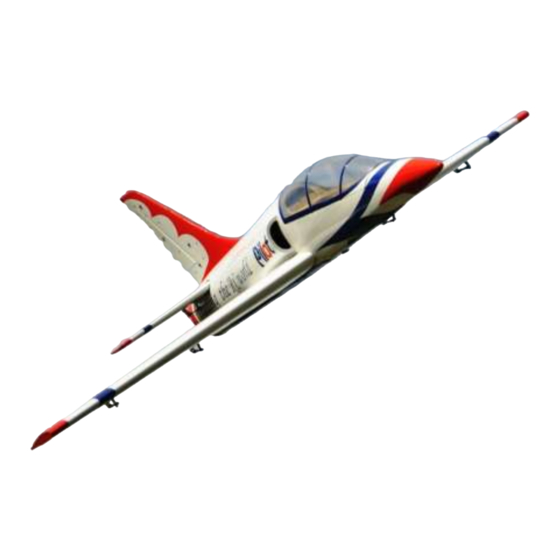
- Page 1 Assembly Manual For Dolphin Jet...
- Page 2 INTRODUCTION Thank you for purchasing our Dolphin Jet. we strive to achieve the real Quick Builded and ARF aircraf . It just requires the least about of assembly of any kit that almost finished in factory. To obtain the perfect...
-
Page 3: Warranty
WARRANTY ■ All Pilot-RC products are guaranteed against defects for 30 days of receiving your airplane. This warranty is limited to construction or productions defects in both material and workmanship , doesn't cover any component parts damaged by use or modification . ■... - Page 4 ATTENTION ■ You should not regard this plane as toy! ■ To ensure safety,please read the instruction manual thoroughly before assembly . ■ Building and operating model plane require diligent practicing and correct guidance. Any neglect,carelessness and missing experience can cause serious bodily harm and property damage.
- Page 5 Landing Gear Assembly Retract Landing Gear Installation...
-
Page 6: Landing Gear Assembly
Landing Gear Assembly 3. Connect the air tube to the retract 1, Install the servo to the nose gear as the photo shows. Note to use landing gear. the different color tube. Red for brake, green and orange for the retract gear. 4. - Page 7 Landing Gear Assembly 5. Install the air throttle as the photo shows. 7. Install the nose retract gear to the fuselage. 6. Install the check valve, brake valve, retract valve, fuel dot, air pressure guage as the photo show. Install the servo for brake and retract valve.
- Page 8 Landing Gear Assembly 8. Find the hole between the flap 9. Put the retract gear air tube from servo bay and the retract gear bay. the flap servo bay to the root of the wing . There is a tunnel under the covering as the photo shows.
- Page 9 Landing Gear Assembly 11. Screw the retract gear to the 13. Cut the covering around the retract gear bay in the wing. Fix the retract gear bay. brake air tube as photos shows. 12. Get the plastic landing gear cover. 14.
- Page 10 Landing Gear Assembly 15. Put the retract gear plastic cover into the retract gear bay. 16. Apply the instant adhesive to glue the plastic cover to the wing.
-
Page 11: Wing Servo Assembly
Wing Servo Assembly 2. Trace around the locking plate Aileron/falps Control Horns with kinfe and cut off the cover below.Then the pre-cut slots appear 3. Scuff the horns with a piece of 1. Tear off the cover on the horns sand paper for good glue bond.Then and locking plates clean up the surface... -
Page 12: Servo Installation
Wing Servo Assembly 4. Apply the 30 minutes epoxy Servo Installation inside the pre-cut slot for horn ,and coat the horn with epoxy as shown 1. Cut out the cover for servo 5. Slide the horn into slot slightly location carefully .Tape the lead to and Mount the locking plate in pull-string tightly. - Page 13 Wing Servo Assembly 2. Lock the connector with the 5. Find four sets of servo mounting provided safety clip against vibration plate. and loosened tension as shown 3 Then put the extention lead 6. Glue two piece of wood to the through the root of wing servo mounting plate as shown Note: Be sure to glue it strong enough.
- Page 14 Wing Servo Assembly 7. Use 1mm bit to drill the mounting 8. Install the servo arms facing holes. Then screw four bolts to fix toward the wing edge and adjust the servo to the servo mounting. pushrod in proper length to keep the aileron panel on the neutral position 8.
-
Page 15: Elevator Servo Assembly
Elevator Servo Assembly 2. Trace around the locking plate Elevator Control Horns with kinfe and cut off the cover below.Then the pre-cut slots appear 1. Tear off the cover on the horns 3. Scuff the horns with a piece of and locking plates sand paper for good glue bond.Then clean up the surface... - Page 16 Elevator Servo Assembly 4. Apply the 30 minutes epoxy Servo Installation inside the pre-cut slots, and coat the horn with epoxy as shown 5. Slide the horns into slots slightly and Mount the locking plate in 1. Cut off the cover on the pre-cut place.
- Page 17 Elevator Servo Assembly 2. Install servos with mounting screws. Face the brand toward the rear of fuse. 3. Install the servo arm with mounting screw and make it vertical with ground. Adjust pushrod in proper length to keep the aileron panel on the neutral position...
- Page 18 Elevator Servo Assembly 7. Repeat all the step above for the 6. Install the stab with mounting bolts and washers other stabilizer...
-
Page 19: Rudder Servo Assembly
Rudder Servo Assembly 2. Trace around the locking plate Rudder Control Horns with kinfe and cut off the cover below.Then the pre-cut slots appear 3. Scuff the horns with a piece of 1. Tear off the cover on the horns sand paper for good glue bond.Then and locking plates clean up the surface... - Page 20 Rudder Servo Assembly 4. Apply the 30 minutes epoxy Servo Installation inside the pre-cut slot for horn ,and coat the horn with epoxy as shown 1. Cut out the cover for servo 5. Slide the horn into slot slightly location carefully .Tape the lead to and Mount the locking plate in pull-string tightly.
- Page 21 Rudder Servo Assembly 2. Lock the connector with the 5. Find four sets of servo mounting provided safety clip against vibration plate. and loosened tension as shown 3 Then put the extention lead 6. Glue two piece of wood to the through the root of rudder servo mounting plate as shown Note: Be sure to glue it strong enough.
- Page 22 Rudder Servo Assembly 7. Use 1mm bit to drill the mounting 8. Install the servo arms facing holes. Then screw four bolts to fix toward the rudder edge and adjust the servo to the servo mounting. pushrod in proper length to keep the aileron panel on the neutral position 8.
- Page 23 Fin accembly Note: Must be sure the fin is vertical with the stabilizer. 1, Glue the fin to the fuselage with the 30 minutes epoxy. Apply the 30 minutes epoxy 2, There some small piece of covering to seal the gap between the fin and the fuselage.
-
Page 24: Fuselage Assembly
Fuselage Assembly Tail pipe Installation 1, Find the tail pipe fixing wood. 2, Fix the front of the tail pipe to Fix to the tail of the fuselage the fuselage by four bolt. by six bolt. Not Include... - Page 25 Fuselage Assembly The wing servo wire and retract air There are precut hole on the tube go through the bottom of the fuel fuselage for all the wire . Show as tank. Show and the photos. the following photo. Wing retract air tube and servo wire...
- Page 26 Fuselage Assembly Install the air tank, flow air trap tank, Mount the turbine to the fuselage. fuel pump on the first floor under the Please note the gap should be 2cm canopy as the photo show. as the photo shows. Screw two set of wood to the 2 floor understand the canopy.
-
Page 27: Cockpit Assembly
Cockpit Assembly Put the cockpit into the canopy. Apply The Dolphin jet come with the the instant adhesive to glue it. cockpit . It does not preinstall in factory so you can put the pilot and instrument board in the cockpit. - Page 28 Navigate Light Assembly Note: Navigate Light sell separately, Total 7 LED light as shown below Not come with the plane. You can Email Tony (info@pilot-rc.com) to by...
- Page 29 Navigate Light Assembly Note: The LED light connect as shown. 1, the LED light only use 7.4V battery. 2, The LED light can work without radio control switch. It will power on once you connect the power to the LED light. 3, If you want to use the switch by radio control.
- Page 30 Navigate Light Assembly Tail LED light : Rudder LED light : Nose landing gear LED light :...
- Page 31 Navigate Light Assembly Fuselage bottom LED light : Nose landing gear LED light : Fuselage top LED light :...
-
Page 32: Cg And Control Throws
CG And Control Throws Center Of Gravity The First Flight set up The center of gravity is marked on the root of the wing. Near to Adjust idle –full Throttle: the wing tube as shown. Elevator: 25 Degrees on High rate 12 Degrees on Low rate Aileron: 25 Degrees on High rate... -
Page 33: Flight Preperation
Flight Preperation Make sure you have the right model programmed into your ■ transmitter Check the direction of each surface not and also right before ■ you take off . Remember nothing wrong on the ground ever improves in ■ the air Check the air plane with the engine running and do a range ■...
Need help?
Do you have a question about the Dolphin Jet and is the answer not in the manual?
Questions and answers