
Related Manuals for Pilot Communications 50cc


Summary of Contents for Pilot Communications 50cc
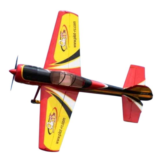
- Page 1 Assembly Manual For 50cc aerobatic plane 50cc aerobatic plane Wingspan: 88 in Wingarea: 1479.8 sp in Length: 78.8 in Engine: 50CC www.pilot www.pilot- - rc.com rc.com...
-
Page 2: Introduction
INTRODUCTION Thank you for purchasing our new 50cc aerobatic plane. we strive to achieve a good quality quick build ARF aircraft . It requires the least amount of assembly of any ARF kit to obtain the maximum performance. Both the design and manufacturing... -
Page 3: Warranty
WARRANTY WARRANTY ■ All Pilot-RC products are guaranteed against defects for 30 days of receiving your airplane. This warranty is limited to construction or production defects in both material and workmanship , it does not cover any component parts damaged through use or modification . -
Page 4: Attention
ATTENTION ATTENTION Do not regard this plane as a toy! ■ ■ To ensure safety, please read the instruction manual thoroughly before assembly. ■ Building and operating an RC Plane of this nature requires previous experience and competence to an experienced level. -
Page 5: Table Of Contents
INDEX Introduction ………………….………..….…….…. Warranty …………………….……..….…..……. Attention …………….…………..….……..……. Fuselage Unit Rudder Assembly Rudder Control Horns ………..…….…...…….. Tail Wheel Installation …………..……..Rudder Axis Installation …….……...….…….. Landing Gear Assembly Main Landing Gear Installation ………….…..……. Pants Installation …………..….……… Servo Unit Wing Servo Assembly Servo Arm Installation ………….….………. -
Page 6: Fuselage Unit
Fuselage Unit Rudder Assemby Rudder Control Horn 2. Trace around the locking plate 1. Tear off the cover on the horns with knife and cut off the cover (see and locking plates below). Then the pre-cut slots appear... - Page 7 Rudder Assembly 3. Scuff the middle of horns with a 5. Slid the horns into slots slightly, piece of sand paper for good glue mount the locking plates in place.Wipe bond.Then clean up the surface away excess glue with rubbing alcohol 6.
-
Page 8: Tail Wheel Installation
Rudder Assembly 2. Drill holes on the tail wheel Tail Wheel Installation mounting block accordingly with the tail wheel strut taped in place or mounted with one bolt as shown 3. Install the blind nuts through the 1. Draw a center line with a pencil opening in the rear of the fuselage as shown and fit screws for the tail wheel... - Page 9 Rudder Assembly 4. Install the hatch over the opening in Ensure the spring has been fitted the rear of fuselage with the 4 screws tightly for correct operation of tail in line with the pre-drilled holes wheel when rudder operates 5.
-
Page 10: Rudder Axis Installation
Rudder Assembly 2. Align the rudder in place inserting the steering arm through the steering Rudder Axis Installation tube in top of rudder ensure pin bent end sits flush on top of rudder This demountable rudder design could offer more room for you to ship and store 1. -
Page 11: Landing Gear Assembly
Landing Gear Assembly Main Landing Gear Installation NOTE: the correct edge in mounting Taper to rear Straight edge to front of fuse... - Page 12 Landing Gear Assembly 1. Install the landing gear with 3. Lift the rear of fuse to line it up supplied bolts and locking nuts with ground as shown Note: Don’t over tighten and crack the carbon fiber 4. Make the flat sides of the axle bolt 2.
-
Page 13: Pants Installation
Landing Gear Assembly 5. Install the collars and wheels in 2. Drill the holes for the mounting correct order, use a drop of Blue bolts and install the blind nuts. Loctite on the collar set screw. Ensure the wheel freely rotates. Pants Installation 3. -
Page 14: Servo Unit
Servo Unit Wing Servo Assembly Servo Arm Installation 2. Ensure the servo arm is 90 degrees to servo as shown. Then Minimum Request Servo: mark and drill holes with 2mm bit. 180 in.zo / Metal Gear / Digital Note: Refer to your radio manual , set sub-trims and end points to obtain equal throws on both wing servos in all directions. -
Page 15: Aileron Control Horns
Wing Servo Assembly 2. Trace around the locking plate Aileron Control Horns with kinfe and cut off the cover below.Then the pre-cut slots appear 3. Scuff the horns with a piece of 1. Tear off the cover on the horns sand paper for good glue bond.Then and locking plates clean up the surface... -
Page 16: Servo Installation
Wing Servo Assembly Servo Installation 4. Apply the 30 minutes epoxy inside the pre-cut slot for horn ,and coat the horn with epoxy as shown 5. Slide the horns into slot slightly and Mount the locking plate in 1. Cut out the cover for servo location place. - Page 17 Wing Servo Assembly 2. Lock the connector with the 4. Then put the extention lead provided safety clip to prevent through the root of wing disconnection during use. 5. Install servo with mounting 3. Tape the lead to pull-string screws. Face the brand toward the tightly.
- Page 18 Wing Servo Assembly 6. Install the servo arms facing 7. Repeat all steps above for the toward the wing tip and adjust other wing pushrod to correct length to keep the The carbon tube and wing bolts are aileron in the neutral position. used to mount wings to fuselage in (Connect servo, turn on radio to centre servo reset pushrod as required)
-
Page 19: Rudder Servo Assembly
Rudder Servo Assembly Servo Tray Installation Minimum Request Servo: 2. Drill 2mm holes for screws 180 in.zo / Metal Gear / Digital 1. Turn on transmitter, plug servo into 3. Mounting screws and nuts rudder slot on receiver. Ensure trim set to neutral. -
Page 20: Servo Installation
Rudder Servo Assembly Servo Installation 2. Tape the rudder panel to top of the vertical fin in the neutral position The rudder cables and couplers have to make it straight been installed as shown 1. Mount servo with mounting Turn on radio to centre the servo. screws and face the brand label Attach the pre-installed ball link to toward the rudder. - Page 21 Rudder Servo Assembly 4. Mount the pre-installed ball link to 5. Crimp the brass tubes with crimping the rudder servo arm without locking pliers once satisfied alignment is nut. Put two brass tubes on the cable correct and thread through the coupler hole. Ensure the cables are straight NOTICE: The coupler thread is 6.
- Page 22 Rudder Servo Assembly 7. Thread the coupler in 2 – 4 mm. 9. Remove the ball links from Ensure the same length of cables rudder horn and install the servo and tension arm ball links with bolts and nuts 2-4mm Turn off radio now.
-
Page 23: Elevator Servo Assembly
Elevator Servo Assembly Servo Arm Installation 2. Ensure the servo arm is 90 degrees with servo as shown. Then mark and drill 2mm holes Minimum Request Servo: 180 in.zo / Metal Gear / Digital Pre fasten the arm with drops of fast cured gule on edge 1. -
Page 24: Elevator Control Horns
Elevator Servo Assembly 2. Trace around the locking plate Elevator Control Horns with kinfe and cut off the cover below.Then the pre-cut slots appear 1. Tear off the cover on the horns 3. Scuff the horns with a piece of and locking plates sand paper for good glue bond.Then clean up the surface... -
Page 25: Servo Installation
Elevator Servo Assembly Servo Installation 4. Apply the 30 minutes epoxy inside the pre-cut slot for horn ,and coat the horn with epoxy as shown 5. Slide the horns into slots slightly 1. Lock the connector with the and Mount the locking plate in provided safety clip against vibration place. - Page 26 Elevator Servo Assembly 2. Thread the extension lead through 4. Cut the cover to expose the pre- fuselage drilled hole for mounting horizontal stabilizer to fuselage 3. Install servos with mounting 5. Install the stabilizer with screws. Face the brand name toward mounting bolts &...
- Page 27 Elevator Servo Assembly 6. Install the servo arms facing 7. Repeat all the step above for the toward the ground, adjust pushrod to other stabilizer correct length so elevator panel is in the neutral position.
-
Page 28: Switch Assembly
Switch Assembly Switch Installation 1.cut off the cover film flush with a sharp knife Note: The switch mounting holes have been pre-cut for standard size 2. Fit supplied switch nuts and bolts. switch. If required adjust hole size by using 1.7mm plywood glued on inside and cut hole to match your preferred switch. -
Page 29: Engine Unit
Engine Uint Firewall Assembly Move if necessary 1. Measure the length of the engine Note: The 2 degree right thrust is (from the firewall to the prop thrust built in at time of fixing firewall, washer), the cowl and the engine ensure you align the firewall the box for the proper distance allowing same distance from each fuselage... - Page 30 Firewall Assembly 2. Drill the firewall according to the 4. Epoxy the firewall with 30 minutes pre-marked laser holes for DA 50.3W epoxy and use the mounting screws 50, or to suit the engine you use, note and lock nut to fasten it immediately as the offset of the holes to allow for side shown thrust &...
-
Page 31: Engine Assembly
Engine Assembly Engine Installation Throttle Servo Installation Not Include Remember: Only use Blue Loctite on 1. Install the engine throttle arm all engine mounting screws once you with a little Blue Loctite and mark have installed the throttle servo and the throttle pushrod hole and fuel drilled the fuel line hole in firewall, line location ,then drill as shown... - Page 32 Throttle servo Installation 2. Measure and cut off throttle 4. Cut away the marked location as pushrod extra wire and bend to a shown. Make surpports with the cut sharp “z” to fit servo arm. Mount the off plywood in 2 layers and epoxy into throttle pushrod to engine.
-
Page 33: Muffler Assembly
Muffler Assembly 2. Epoxy the bracker in place Canister Bracket Installation supported by triangular hardwood supports 3. Mount the silicon vibration 1. Use a sharp knife to remove the insulators. Use soldering iron remove cover from the canister pre-cut air the fuselage hatch covers and finish exit opening and ensure the edge mounting with self-tapping screws. -
Page 34: Muffler And Canister
Muffler Assembly Muffler And Canister 2. Tighten the muffler mounting bolts with Blue Loctite 1. Bend the pipe and trial fit till align 3. Use silicone coupler on exhaust the canister. Then cut the excess joint securing with clamps as shown pipe to correct length... -
Page 35: Ignition Module
Ignition Module 2. Position the ignition outside the Ignition Module engine box to allow the spark plug leads to connect the engine without excess tension, drill hole for nylon cable tie. 1. Use single sided self adhesive 3. Lock the connectors with the foam rubber on bottom of ignition provided safety clip to prevent unit and attach to plywood side as... -
Page 36: Hatch And Fuel Tank
Hatch And Fule Tank Fule Tank And Dot Engine Box Hatch Fule Fill Line Fule line Epoxy the hatch in place and secure Fuel tank and fuel dot has been with self-tapping screws installed. Tighten the Velcro ties when finally positioned. -
Page 37: Cowl Assembly
Crowl Assembly 2. Use a fiber cutting tool to rough Crowl Assembly cut the cowl and finish with a round sander 1.Measure the center of the spark plug and make a pattern of the 3. Cut out hole for the exhaust pipes engine head on a paper template and muffler you use, with clearance and follow required cut out shape. - Page 38 Crowl Assembly 4. Ensue all corners are rounded 6. Install into position using the and not a sharp 90 degree corner to bolts. There are two that mount minimize any splitting under from the rear of the firewall on the vibration.
-
Page 39: Cg And Control Throws
Center of gravity Center Of Gravity The center of gravity is on the rear of the wing tube. For other planes refer to the CG list below Your balance at the correct CG can be determined by positioning batteries in correct location. Mount batteries and secure with nylon ties... - Page 40 Center of gravity The CG list of Pilot-RC products This recommendation balance point is for PLANE CG location your first flight.The CG can be moved around to fit your personal taste. DECATHLON 107” 133mm/5.2inch DECATHLON 122’’ 145 mm/5.7inch DECATHLON 150’’ 182 mm/7.2inch Columbia 400 128’’...
-
Page 41: Control Throws
Control Throws The First Flight set up Throttle: Adjust idle –full Elevator: 40 Degrees on High rate 12 Degrees on Low rate Aileron: 30 Degrees on High rate 12 Degrees on Low rate Rudder: 45 Degrees on High rate 40 Degrees on Low rate After you have set the given control ■... -
Page 42: Flight Preparation
Flight Preperation Make sure you have the right model programmed into your ■ transmitter Check the direction of each control surface for correct ■ operation before you take off . Remember nothing wrong on the ground ever improves in ■ the air Check the air plane with the engine running and do a range ■...
Need help?
Do you have a question about the 50cc and is the answer not in the manual?
Questions and answers