Advertisement
Quick Links
A S S E M B L Y I N S T R U C T I O N S
TABLE OF CONTENTS:
Pg. 1
Pg. 1
Assembly
Pg. 2 - Pg. 11
Pg. 9
Pg. 13
Exploded View Diagram
Fold-out Pg. 14
Cable Mapping Diagram
Fold-out Pg. 15
Back Page
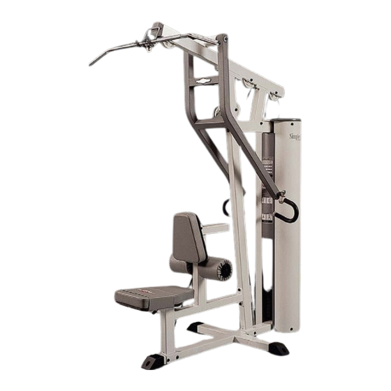
SP-404
Lat/Mid-Row
© 2003 TuffStuff Fitness Equipment, Inc.
A m e r i c a ' s P r e m i e r E x e r c i s e E q u i p m e n t
48"
L 61 1/2" W 48" H 82 3/4"
Revision Date 05-29-02
61 1/2"
SP-404 Rev0
Advertisement

Related Manuals for TuffStuff SP-404


Summary of Contents for TuffStuff SP-404
-
Page 1: Table Of Contents
A m e r i c a ’ s P r e m i e r E x e r c i s e E q u i p m e n t © 2003 TuffStuff Fitness Equipment, Inc. SP-404 Rev0... -
Page 2: Introduction
Stuff Equipment This Tuffstuff product has been built to precise quality 2. Neatly organize and identify all parts according to the standards and has been carefully packaged to ensure that Parts List and the Exploded View Diagram. - Page 3 Rubber Donuts (#12). Note: Be sure the label on the Top Plate Selector Bar (#6) facing out, as shown above, before sliding the Top Plate Se- lector Bar (#6) onto the Guide Rods (#3). SP-404 Lat/Mid-Row...
- Page 4 Hex Head Cap (#5) in the corresponding order. Begin with the 20 at the top, 30 next, Screws 1/2-13 X 3 1/2 (#20), four Flat Washers SAE 1/2” (#25), and and so on. two Nylon Insert Lock Nuts 1/2-13 (#18). SP-404 Lat/Mid-Row...
- Page 5 1/2” (#25). Using a rubber mallet, insert the Pivot Axle (#37) through the receptacles of the Press Bar (#29) and the Top Pulley Assembly (#28) until it be- comes flush with both sides of the Press Bar (#29). SP-404 Lat/Mid-Row...
- Page 6 Note: The black boxed letter pointing to the pulleys are used throughout this manual as reference to the Cable Mapping Dia- gram on fold-out page 15. These black boxed letters will be primarily used for locating certain pulleys during the cable rout- ing process beginning with Fig. 16. SP-404 Lat/Mid-Row...
- Page 7 Labeled F) and attach the pulley to the Top Pulley Assembly (#28) using one Hex Head Cap Screw 3/8-16 X 2 1/2 (#21), two Flat Wash- ers SAE 3/8” (#15), and one Nylon Insert Jam Lock Nut 3/8-16 (#19). SP-404 Lat/Mid-Row...
- Page 8 Note: Refer to Fig A on fold-out page 15 for further detailed il- lustration of this assembly. FIG. 23 Connect the Lat Bar (#43) to the Cable (#42) using the FIG. 24 Rest the Lat Bar (#43) onto the Lat Bar Holder (#36) when not in use. Snap Link (#85). SP-404 Lat/Mid-Row...
- Page 9 Attach the two Metal Hinges (#57) to the axle of the Adjust- able Chest Pad Tube (#32). Be sure to position the Metal Hinges (#57) (#31) using four Hex Head Cap Screws 3/8-16 X 1 1/4 (#65), and four as shown above. Flat Washers SAE 3/8” (#15). SP-404 Lat/Mid-Row...
-
Page 10: Cable Adjustment
3. Re-tighten the Finished Hex Nut 1/2-13 (#80) to complete the adjustment. Caution: Make sure the Cable Hex Tap Bolt 1/2-13 X 3 (#79) is threaded at least 1/2” into the threaded socket of the Top Plate Selector Bar (#6) once the cable adjustment has been completed. SP-404 Lat/Mid-Row... - Page 11 Plastic Shroud Gap Cover (#7) and the Plastic Shroud Edge Stack Frame (#1) and at the top of the Guide Rod Retainer (#4) Protectors (#9). ing four Hex Head Cap Screws 1/4-20 X 3/4 (#17), and four Flat Washers 1/4” (#16). SP-404 Lat/Mid-Row...
- Page 12 FIG. 39 Secure the Plastic Shroud Lid (#8) to Guide Rod Retainer (#4) using two Flat Head Socket Cap Screws 3/8-16 X 3 (#23). SP-404 Lat/Mid-Row...
- Page 13 N o t e s SP-404 Lat/Mid-Row...
-
Page 14: Parts List
BNH0052 PLASTIC SHROUD GAP COVER BNH1083 PLASTIC INSERT CAP 2" SQ. BNH0012 PLASTIC SHROUD LID 5/8 X 14 1/8 X 10 (SP-404) BNH1181 PLASTIC END CAP 2 X 3 (SIMPLEX LINE) BNH0606 PLASTIC SHROUD EDGE PROTECTOR 1/8 X 26 3/4... - Page 15 SP-404 Lat/Mid-Row...
-
Page 16: Warranty
L I M I T E D W A R R A N T Y TuffStuff warrants to the original purchaser only that TuffStuff equipment will be free from defects in material and workmanship. The warranty and remedies set forth herein are conditioned upon proper storage, installation, use, maintenance and conformance with any recommendations of TuffStuff.
Need help?
Do you have a question about the SP-404 and is the answer not in the manual?
Questions and answers