Advertisement
Quick Links
A S S E M B L Y I N S T R U C T I O N S
TABLE OF CONTENTS:
Pg. 1
Pg. 1
Assembly
Pg. 2 - Pg. 9
Pg. 8
Cable Mapping Diagram
Fold-out Pg. 10
Exploded View Diagram
Fold-out Pg.11
Pg. 12
Back Page
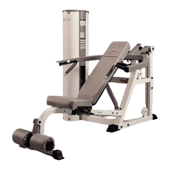
SP-403
Multi-Press
© 2003 TuffStuff Fitness Equipment, Inc.
A m e r i c a ' s P r e m i e r E x e r c i s e E q u i p m e n t
81 3/4"
L 81 3/4" W 55" H 54 3/4"
Revision Date 06-16-04
55"
SP-403 Rev1
Advertisement

Related Manuals for TuffStuff Multi-Press SP-403


Summary of Contents for TuffStuff Multi-Press SP-403
-
Page 1: Table Of Contents
A m e r i c a ’ s P r e m i e r E x e r c i s e E q u i p m e n t © 2003 TuffStuff Fitness Equipment, Inc. SP-403 Rev1... -
Page 2: Introduction
Stuff Equipment 2. Neatly organize and identify all parts according to the This Tuffstuff product has been built to precise quality Parts List and the Exploded View Diagram. standards and has been carefully packaged to ensure that damage will not occur during shipment. - Page 3 Owner’s Manual: Assembly Instructions FIG. 1 On a flat surface, attach the Bottom Cross Brace (#38) FIG. 2 Remove the Guide Rod Retainer (#5), and the Top Plate the assembled Weight Stack Frame (#1), in the position as shown Selector Bar (#9) to allow the assembly of the weight plates.
- Page 4 FIG. 5 Maneuver the two Guide Rods (#4) into the holes on the FIG. 6 Locate the Selector Pin w/Coil (#94) and slide the ring over bottom side of the Guide Rod Retainer (#5). Next, secure the Guide Selector Bar (#9) as shown above.
- Page 5 Owner’s Manual: Assembly Instructions Cable Fishing String Cable Fishing String FIG. 9 To facilitate the routing of the Cable (#87) through the Bot- FIG. 10 Pull the Cable Fishing String along with the Cable (#87) tom Cross Brace (#38) use the supplied Cable Fishing String. Tie a through the Bottom Cross Brace (#38) as shown above.
- Page 6 FIG. 13 Using a rubber mallet, insert two Plastic End Caps 2 X 3 FIG. 14 Affix the Rear Cross Brace (#39) to the Press Bar Main (#53) onto the tube-ends of the Press Bar Main Frame (#32). Next, Frame (#32) using two Hex Head Cap Screws 1/2-13 X 4 3/4 (#84), attach the Press Bar Main Frame (#32)
- Page 7 Owner’s Manual: Assembly Instructions FIG. 17 Route the Cable (#87) under the Nylon Pulley 4 1/2 Rd. FIG. 18 Insert a Split Lock Washer Z/P 1/2” (#66) to the Cable Hex (#16-Labeled D) and attach it to the Press Bar Main Frame (#32) Bolt 1/2-20 X 1 (#90) then thread the Rod End 1/2-20 (#89) to the Ca- pulley bracket using one Hex Head Cap Screw 3/8-16 X 2 (#26), two ble Hex Bolt 1/2-20 X 1 (#90).
- Page 8 FIG. 21 Secure the Press Bar (#31) to the Press Bar Pivot Axle FIG. 22 Affix the Back Pad (#44) to the Bench Back Pad Frame (#34) using two Socket Set Screws 1/4-20 X 1/4 (#86). Use the sup- (#36), in the position as shown above, using two Flat Head Socket plied Hex Key 1/8”...
-
Page 9: Cable Adjustment
CABLE ADJUSTMENT It is imperative that you maintain proper cable adjustment to ensure Caution: The Cable should be inspected and adjusted peri- a safe and smooth operation. odically to avoid any slack in the cable which would, conse- quently, prevent any damage to the equipment or personal in- jury. - Page 10 FIG. 27 Align the edges of both Shrouds (#2, #3) with the grooves FIG. 28 Connect the two Plastic Shroud Edge Protectors (#12) to of the Plastic Shroud Gap Cover (#10) and slide it down, as shown the Plastic Shroud Gap Cover (#10) using the two Plastic Connectors above.
-
Page 11: Parts List
BENCH SEAT PAD UP0444 DECAL-SIMPLEX II (1 7/8 X 5 3/16) BNH1199 BENCH BACK PAD UP0445 DECAL-TUFFSTUFF (2 3/4 X 19 1/16) BNH1200 WEAR COVER (OPTIONAL) UP0833 DECAL-EXERCISE SP-403 MULTI- PRESS 4 1/2 X 19 1/4 BNH1188 FOOT ROLL 1 X 5 1/2 X 7 1/4... -
Page 12: Warranty
L I M I T E D W A R R A N T Y TuffStuff warrants to the original purchaser only that TuffStuff equipment will be free from defects in material and workmanship. The warranty and remedies set forth herein are conditioned upon proper storage, installation, use, maintenance and conformance with any recommendations of TuffStuff.
Need help?
Do you have a question about the Multi-Press SP-403 and is the answer not in the manual?
Questions and answers