Table of Contents
Advertisement
Quick Links
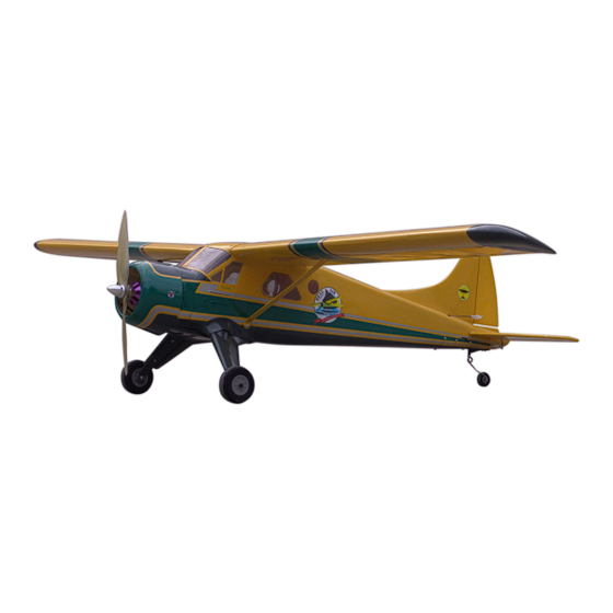
Electric Beaver
Specification:
Length
:958 mm(37.7")
Wing Span
:1500 mm(59.1")
Wing Area
:23.5 sq. dm
2.53 sq. ft
wing loading
:89.4 g/sq. dm
29.3 oz/sq. ft
flying weight
:2.1kg(4.62 lbs)
Radio
:4ch& 4servos
:600rpm/v
Motor(KV)
42x50mm
Battery
:Li-PoX4 (2000mAh)
Motor controller
:45A
SAFETY PRECAUTIONS
INSTRUCTION MANUAL
This R/C airplane is not a toy!
(The people under 18 years old is forbidden from flying this model)
First-time builders should seek advice from people having building
experience.If misused or abused,it can cause serious bodily injury
and damage to property.
Fly only in open areas and preferably at a dedicated R/C flying site.
We suggest having a qualified instructor carefully inspect your
airplane before its first flight.Please carefully read and follow all
instructions included with this airplane,your radio control system
and any other components purchased separately.
Advertisement
Table of Contents

Subscribe to Our Youtube Channel
Related Manuals for Troy Built Models Electric Beaver


Summary of Contents for Troy Built Models Electric Beaver
- Page 1 Electric Beaver Specification: Length :958 mm(37.7") Wing Span :1500 mm(59.1") Wing Area :23.5 sq. dm 2.53 sq. ft wing loading :89.4 g/sq. dm 29.3 oz/sq. ft flying weight :2.1kg(4.62 lbs) Radio :4ch& 4servos :600rpm/v Motor(KV) 42x50mm Battery :Li-PoX4 (2000mAh) INSTRUCTION MANUAL...
- Page 2 Centre of Gravity. The side view when the model assemble completely. (with 9 servos), 6 channel radio for aiplane is highly recommended for this model. 53mm The full model side view when install completion. : 4-cycle .120 Spinner nut " Pre-cover the covering with clean cloth! Warning Start at low setting.
- Page 3 Epoxy the wooden block to the fuselage Adjustment. Accessory list for the coming installation steps. Assemble the aileron to main wing with instant type CA glue. Be careful under the top hatch. to ensure the moving parts of the hinges are able to move freely. Clevis Retainer Rod (2x300mm)
- Page 4 Assemble the other side of the wing strut to the Install the servo as illustration below. The position of the control horn in the aileron. The standard sketch map of the wings installation finished. fuselage with screw. A" Set screw (3x4mm) A = A"...
- Page 5 Set the rib templates to the appropriate position on the Accessory list for the coming installation steps. Epoxy the PVC parts to the landing gear as below. Fix the PVC part on the fuselage. fuselage and drill holes as below. Pin hinge(24x24mm) U-style wire(100x25mm) Rib template (3mm ply)
- Page 6 Assemble the U-style wire to stabilizer as below. Accessory list for the coming installation steps. Epoxy the frame to appropriate position in the cowl. Epoxy the canopy to the fuselage. Tail landing gear(2mm) Sticker Sticker Tail wheel (25mm) 50mm Collar (2mm) Pin hinge(2.5x48mm) Wooden Block (60x20x3mm)
- Page 7 Assemble the horn to the elevator and connect the Assemble the rod for rudder to the fuselage from the Keep some space with 1mm width between the Epoxy the rudder to the vertical tail edge. linkage to the servo. tailing edge and rudder. pushrod tube in the fuselage as below.
- Page 8 Drill a hole to appropriate position and epoxy the Drill holes and set blind nut in appropriate position and Drill holes and set blind nut in appropriate position in Accessory list for the coming installation steps. pushrod in it. assemble the main landing gear. the firewall before install the motor mount.
Need help?
Do you have a question about the Electric Beaver and is the answer not in the manual?
Questions and answers