Table of Contents
Advertisement
Quick Links
70
Adjustment.
Side View
RUDDER
40mm
40mm
Top view
Two wheel retract system
Make sure to assemble retracts as instructed below.
3-way
Strut
pressure inlet
3-way
pressure inlet
Quick release connector
Pressure reduction inlet
Ø1.7mm
Please insure the sealing of theretract
system before flight .
Pleas notice the inner diameter
of eachside the pressure reduction inlet.
o
Switch
Strut( 90 )
1
2
Air line (3000mm)
1
Retainer
3-way pressure inlet
1
3
Air tank
Clevis
1
1
Air inlet
1
Rod (2X300mm)
Quick release connector
1
2
Pressure reduction inlet
TP Screw(2x14mm) 2
1
71
The centre of the Gravity.
120mm
3-way
pressure inlet
Air inlet
Air tank
Quick release connector
Ø0.2mm
S w i t ch
Air valve
Air valve
Pull out length of 8mm
The status when the
to make gear down
gear up
14
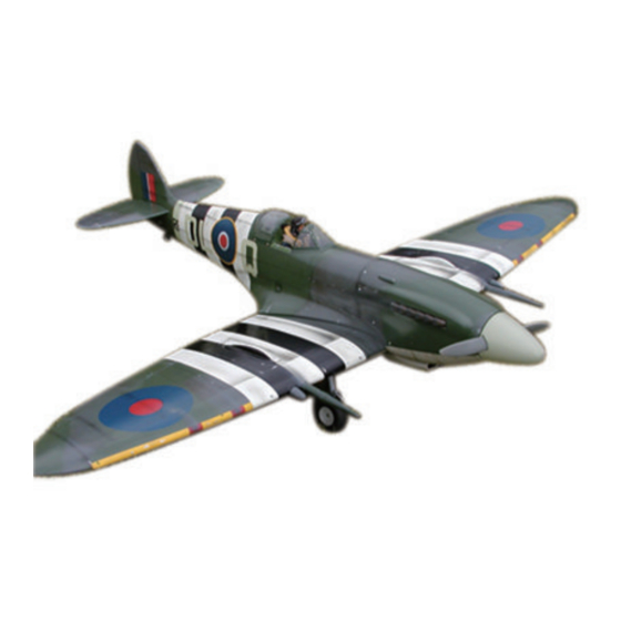
SPITFIRE MK.XIV\XIX
Strut
Specifications:
Wing Span:
1840mm (72 ½" Inches)
Length:
1625mm(64in)
Wing Area:
946sq.in
Wing loading:
33oz/sq.ft
Flying weight:
13 Ibs
Power: ..91 _ 1.20 Two Stroke or .90 - .120 Four Stroke
Radio: 6 Channel w/8 Standard Servos
SAFETY PRECAUTIONS
INSTRUCTION MANUAL
This R/C airplane is not a toy!
(The people under 18 years old is forbidden from flying this model)
First-time builders should seek advice from people having building
experience.If misused or abused,it can cause serious bodily injury
and damage to property.
Fly only in open areas and preferably at a dedicated R/C flying site.
We suggest having a qualified instructor carefully inspect your
airplane before its first flight.Please carefully read and follow all
instructions included with this airplane,your radio control system
and any other components purchased separately.
Advertisement
Table of Contents

Subscribe to Our Youtube Channel
Related Manuals for Troy Built Models SPITFIRE MK.XIV


Summary of Contents for Troy Built Models SPITFIRE MK.XIV
-
Page 1: Instruction Manual
The centre of the Gravity. Adjustment. SPITFIRE MK.XIV\XIX Side View RUDDER 40mm 40mm 120mm Top view Two wheel retract system Make sure to assemble retracts as instructed below. 3-way pressure inlet 3-way Strut pressure inlet Strut Air inlet 3-way Air tank... - Page 2 Epoxy plastic part underneath the wing. Epoxy the landing gear to the wing steadily. TP Screw (2.3x8mm) TP Screw (2.3x8mm) 260mm 1.5mm 6 channel radio for aiplane is highly recommended for this model. 1.5mm 115mm Accessory list for the coming installation steps. Adjustment.
-
Page 3: Table Of Contents
Cut off the surplus part from the cowling,exhausts and Epoxy plies inside the fuselage under the cowing and Assemble the aileron to main wing with instant type CA glue. Be careful Accessory list for the coming installation steps. canopy carefully. mount the cowing with TP screw as illustration. -
Page 4: Table Of Contents
Accessory list for the coming installation steps. The servos installation finished sketch map. Epoxy the pin hinges to the flap. The position of the control horn in the aileron. Clevis Copper joiner switch servo Screw (2x10mm) Elevator servo Nut (2mm ) Washer(2x5mm) Retainer Clevis... -
Page 5: Accessory List For The Coming Installation Steps
Drill holes to the relevant position in the tailing edge Mount the gear door and the wheel to the retract. The sketch map after the rudder shaft assemble finished. The position of the control horn for flap in the wing. and epoxy the rudder to them. - Page 6 Epoxy the PVC decoration parts to the appropriate The sketch map when tail wheel assemble completion. Epoxy the gear house to the relevant position. Accessory list for the coming installation steps. position on the wing as illustration. Steel wire (0.5x1200mm) Retainer 219mm Nose arm(3mm)
-
Page 7: Nut (2Mm )
Trim holes in the appropriate position for draging Assemble the wings to the fuselage with screw Assemble the accelerateor push rod to the engine. Mount the fuel tank to the fuselage. the air tubes and servo lines out. and blind nut as below. Linkage Stopper Set Screw (3x4mm) Screw(6x50mm) -
Page 8: Pin Hinge(24X24Mm)
According to the rib templete drill holes to appropriate Drill holes to appropriate position in the stabilizer and Glue the elevator to the stabilizer by CA and epoxy. Glue the elevator to the stabilizer by CA and epoxy. Glue the elevator to the stabilizer by CA and epoxy. The side sketch map of the engine installation finished.
Need help?
Do you have a question about the SPITFIRE MK.XIV and is the answer not in the manual?
Questions and answers