Advertisement
Quick Links
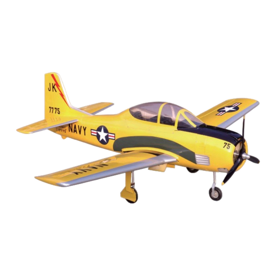
T-28 Trojah
Specification:
Length
:1613 mm(63.5")
Wing Span
:2057 mm(81")
Wing Area
:70.12 sq. dm
7.55 sq. ft
Wing Loading :117 g/sq. dm
39.5 oz/sq. ft
Flying Weight :8.2 kg(18 lbs)
Radio
:6ch & 8 servos
Engine
:180 4-cycle
SAFETY PRECAUTIONS
INSTRUCTION MANUAL
This R/C airplane is not a toy!
(The people under 18 years old is forbidden from flying this model)
First-time builders should seek advice from people having building
experience.If misused or abused,it can cause serious bodily injury
and damage to property.
Fly only in open areas and preferably at a dedicated R/C flying site.
We suggest having a qualified instructor carefully inspect your
airplane before its first flight.Please carefully read and follow all
instructions included with this airplane,your radio control system
and any other components purchased separately.
Advertisement

Subscribe to Our Youtube Channel
Related Manuals for Troy Built Models T-28 Trojah


Summary of Contents for Troy Built Models T-28 Trojah
-
Page 1: Instruction Manual
T-28 Trojah Specification: Length :1613 mm(63.5") Wing Span :2057 mm(81") Wing Area :70.12 sq. dm 7.55 sq. ft Wing Loading :117 g/sq. dm 39.5 oz/sq. ft Flying Weight :8.2 kg(18 lbs) INSTRUCTION MANUAL Radio :6ch & 8 servos Engine :180 4-cycle... - Page 2 6 channel radio for aiplane is highly recommended for this model. 4-cycle .180 Optional parts: rubber wheel with metal hub. Spinner nut 18″X10 We strongly recommen you use the thread lock for all the screws when you build your model.
- Page 3 Assemble the aileron to main wing with instant type CA glue. Be careful Accessory list for the coming installation steps. to ensure the moving parts of the hinges are able to move freely. Three wheel retract system Clevis Retainer Rod (2x300mm) Make sure to assemble retracts as instructed below.
- Page 4 Epoxy the fixed landing gear to the relevant Secure the servo.Install the nylon control horn Keep some space about 1mm width between Adjustment. position in the fuselage. and connect the linkage. trailing edge and flap. TP Screw (2.3x12mm) Trailing edge 1.5mm Side View Flap...
-
Page 5: Accessory List For The Coming Installation Steps
Drill holes to appropriate position in the belly pants and the Assemble the wheel and gear door to landing gear. Mount the gear door and the wheel to the retract. Install the nylon control horn and connect the linkage. wings and epoxy the belly pant to the wing as diagram. Collar (5mm) Retainer LockNut(4mm) - Page 6 Epoxy the wood plates to the appropriate position Put the retracts to the wing and find out the relevant Epoxy plies to relevant position inside the fuselage as position the other part of the pin hinge,drill holes in Epoxy the wheel house to the wings carefully. inside the belly cover as picture.
- Page 7 According to the rib template drill holes in one wing and Install the servo of switch. Assembly of the stabilizer. Epoxy the main wing hardly together with wing joiner. epoxy wood dowel in them. Make sure to glue securely. Main wing joiner If not properly glued, a failure in flight may occur.
- Page 8 Drill holes to the relevant position in the tailing edge The sketch map of the linkage for the rudder Assemble the wings to the fuselage with screw Set the U-style wire through the enlarge hole as below. and epoxy the rudder to them. and the tail wheel.
- Page 9 Keep some space about 1mm width between Assemble the retract to the fuselage with Assemble the stablilizers carefwly to fuselage. Mount the servo of nose wheel to the fuselage. elevator and tailing edge. TP Screw as illustration. TP Screw(3x20mm) Stab joiner (12x270mm) Tailing edge Elevator...
- Page 10 Assemble the throttle servo to appropriate Install the engine carefully. Assembly of the fuel tank. The front view of the engine installation finished. position in the fuselage. Screw (4x35mm) Washer (4x8mm) Washer (4x8mm) Air pressure line Fuel spray line Washer (4x8mm) Screw (4x25mm) Spring Washer (4mm) Fuel supply line...
Need help?
Do you have a question about the T-28 Trojah and is the answer not in the manual?
Questions and answers