
Subscribe to Our Youtube Channel
Related Manuals for Wacker Neuson DPU 6055


Summary of Contents for Wacker Neuson DPU 6055
- Page 1 0109986en 04.2008 Vibratory plate DPU 6055 Operator´s Manual...
- Page 3 Important information This machine has been provided with an EPA-certified engine. Additional information found engine manufacturer‘s notes. WARNING Engine exhaust, some of its constitvents, and certain vehicle components contain or emit chemicals known to the State of California to cause cancer and birth defects or other reproduc- tive harm.
- Page 4 T00940GB.fm...
-
Page 5: Foreword
Foreword Foreword For your own safety and protection from bodily injuries, carefully read, understand and follow the safety instructions in this manual. Please operate and maintain your Wacker machine in accordance with the instructions in this manual. Your Wacker machine will reward your attention by giving trouble-free operation and a high degree of availability. -
Page 6: Table Of Contents
Table Of Contents Foreword Safety instruction General instructions ................6 Operation ....................6 Safety checks ..................8 Maintenance ..................8 Transport ....................9 Maintenance checks ................9 Technical Data Description Applications ..................12 Max. admissible inclination ..............12 Description of function .................13 Transport to work site /Recommendations on compaction Transport to work site ................15 Recommendations on compaction ............17 Operation... - Page 7 Table Of Contents Exciter ....................40 Exciter V-belt ..................42 Faults Forward speed too low ................43 Reverse speed too low ................43 No reverse motion ................43 Loss of hydraulic oil ................43 The charge control lamp will not extinguish ........44 Engine does not start ................44 Electricwirning-Diagramm 10.
-
Page 8: Safety Instruction
Safety instruction Safety instruction for the use of vibratory plates with combustion engines General instructions 2.1.1 Vibratory plates may only be operated by persons who ∗ are at least 18 years of age ∗ are physically and mentally fit for this job ∗... - Page 9 Safety instruction 2.2.3 The function of operation levers or elements is not to be influenced or rendered ineffective. 2.2.4 During operation the operator may not leave the control elements. 2.2.5 The operator has to stop the engine of the vibratory plate before going on breaks.
-
Page 10: Safety Checks
Safety instruction 2.2.16 Vibratory plates are to be guided such that hand injuries caused by solid objects are avoided. 2.2.17 Vibratory plates have to be guided such that their stability is guaranteed. 2.2.18 Machines with integrated transport trolley may not be parked or stored on the trolley. -
Page 11: Transport
Safety instruction 2.4.4 Remove pressure from hydraulic lines before working on them. Caution: take care when removing hydraulic lines, for the oil may be very hot (up. over 80 C). Precautions are to be taken to prevent oil from splashing into the operator’s eyes. 2.4.5 All safety devices must be reinstalled properly immediately after maintenance and repair jobs have been completed. -
Page 12: Technical Data
Technical Data Technical Data DPU 6055 Item no. 0610053 0610049 0610175 Length x width x height 1700 x 710 x 1700 x 860 x 1700 x 710 x 1190 1190 1190 Operating weight without extension plates (550 mm) kg: (610 mm) kg:... - Page 13 Technical Data DPU 6055 Fuel Diesel Fuel consumption l/h: Tank capacity Electrical system Battery Special Wacker-battery for vibro plates - 12 V - 55 Ah Alternator Rotary current generator with electronic regulator and rectifier Charging rate max. Charging voltage Starter Starter motor D.C.
-
Page 14: Description
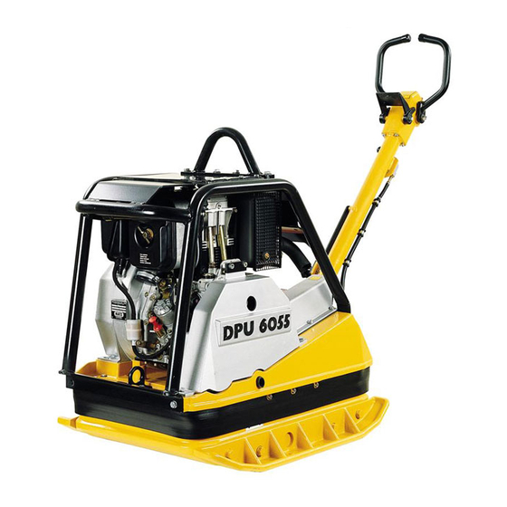
Description Description Applications The vibratory plate has been designed for the compaction of almost every type of soil, both in trenches as well as surface compaction. In addition, it is possible to vibrate paving stones an concrete blocks by using extension plates up to 86 cm (accessories). Extremely cohesive as well as frozen soils are not suitable for compaction. -
Page 15: Description Of Function
Description Description of function 4.3.1 The vibration required for compaction is produced by the exciter (13) which is firmly joined to the lower mass (5). This exciter (13) is designed as a central vibrator with aligned vibrations. Such a principle permits the direction of vibration to be changed by turning the eccentric weights (15). - Page 16 Description 4.3.4 The automatic V-belt pulley (10) combined with the centrifugal clutch (11) ensures optimum tension of the exciter V-belt (12) during operation and relief of the tension of the exciter V-belt (12) when the machine is being relocated or transported. 4.3.5 Moreover, the automatic V-belt pulley (10) automatically adapts to the V-belt flanks in line with the wear and thus makes the entire drive from...
-
Page 17: Transport To Work Site /Recommendations On Compaction
Transport to work site /Recommendations on compaction Transport to work site /Recommendations on compaction Warning Improper use can result in injury or serious material damage. ∗ Read and follow all the safety instructions at the beginning of this operator's manual, see chapter Safety information. Transport to work site Danger Danger of fire and explosions by fuel! - Page 18 Transport to work site /Recommendations on compaction ∗ Only attach suitable tackle at the central lifting point (16) provided. The central lifting point is located exactly above the centre of gravity of the machine. The central lifting point can be displaced rearwards (18), given an application in which the height of the machine is of importance (torque wrench setting = 85 Nm).
-
Page 19: Recommendations On Compaction
Transport to work site /Recommendations on compaction Recommendations on compaction 5.2.1 Ground conditions The max. compaction depth depends on several factors relating to the ground condition, such as moisture, grain distribution etc, it is therefore not possible to specify exact values. Recommendation: In each case determine the max. -
Page 20: Operation
Operation Operation Warning Improper use can result in injury or serious material damage. ∗ Read and follow all the safety instructions at the beginning of this operator's manual, see chapter Safety information. Starting 6.1.1 Starting requirements: Engine oil: Check the oil level with the dipstick (19). Add oil (see Technical data) through the filler neck (21) as needed. -
Page 21: Mechanical Oil Pressure Control
Operation Mechanical oil pressure control It is necessary to reactivate the mechanical oil pressure control in the following cases: ∗ after the initial filling - first filling - of the fuel tank or if the tank has run dry. ∗ in the case of an automatic engine stop due to an inefficient engine oil supply. - Page 22 Operation Check oil level every 8 to 15 operating hours in spite of the mechanical oil pressure control. Warning* Danger of poisoning by exhaust fumes! Exhaust fumes contain toxic carbon monoxide that can lead to unconsciousness or death. ∗ Always switch off the engine during maintenance work! ∗...
-
Page 23: Electric Start
Operation Electric start 1. Turn the throttle control lever (8) clockwise into load position 1/2 - 3/4. 2. Leave decompression lever (2) in the position „e“. 3. Put the ignition key into ignition switch (25) and turn it clockwise into operating position (the charge control lamp (27) lights up and the buzzer will be heard). - Page 24 Operation Wait until the engine stops before repeating the starting procedure. 4. The charge control lamp (27) must turn off immediately after the engine has started running and the acoustic alarm has stopped. Stop the engine immediately in case of eventual irregularities, then locate the fault and repair it.
-
Page 25: Starting The Engine With The Safety Starting Crank
Operation Starting the engine with the safety starting crank 1. Turn the throttle control lever to the load position 1/2 - 3/4. 2. Turn the decompression lever (2) all the way to „f“. At this point automatic decompression lever engages with an audible click, and the engine is ready to start. - Page 26 Operation * Slowly turn the safety starting crank counter-clockwise until the ratchet engages. Then start turning the handle with force and with ever increasing speed. The highest possible turning speed must have been reached when the decompression lever reaches position ”e”...
- Page 27 Operation * Let loose of the safety starting crank immediately and stop the engine if it should start turning in the wrong direction (smoke coming from the air filter) after a back kick. Wait until the engine stops before repeating the starting procedure. 5.
-
Page 28: Starting In Cold Weather
Operation Starting in cold weather Always free the engine if the temperature is less than -5 °C (23 °F). 1. Push the throttle lever (8) to the full throttle position. 2. Turn decompression lever to any position in front of starting position „f“. - Page 29 Operation 5. Clean the area around the dosing device and then pull off the cover. 6. Fill the housing to the upper edge with low viscosity oil. Replace cover and press down with force. Exactly two successive fillings are required. 7.
-
Page 30: Starting With External Battery Etc
Operation Starting with external battery etc. 6.6.1 Essential requirements for battery jumper cable: ∗ Cable cross-section must be at least 16 mm . (2.5 sq. inches). ∗ Clamps must be completely insulated with plastic. Only connect 12 Volt batteries. The on-board battery will explode if connected to a 24 Volt truck battery! The use of starter sprays is absolutely forbidden! External (donor) battery... -
Page 31: Forward And Reverse Motion
Operation Forward and reverse motion The engine speed can be infinitely varied on the throttle control lever. The direction of travel is determinet with the shift lever (6). Depending on the position of the shift lever (6), the vibration plate compacts in forward direction, at standstill or in reverse direction. -
Page 32: Stopping The Engine
Operation Stopping the engine Never switch off the engine with the automatic decompression (2) as this inevitably results in damage to the valve drive and decompression mechanism. 1. Move the throttle control lever (8) to the stop. 2. Turn the ignition key to the stop position and then pull it out once the engine has stopped. -
Page 33: Maintenance
Maintenance Maintenance Warning* Danger of poisoning by exhaust fumes! Exhaust fumes contain toxic carbon monoxide that can lead to unconsciousness or death. ∗ Always switch off the engine during maintenance work! Maintenance schedule Component Maintenance work Maintenance interval approx. 8 hours after Drive engine First oil change and filter. -
Page 34: Engine Oil And Oil Filter
Maintenance Engine oil and oil filter 7.2.1 Check oil level: ∗ Remove dirt from the oil dip stick area. Check oil level on oil dipstick (19). Place the machine in an horizontal (level) position and stop the engine before checking the oil level. ∗... - Page 35 Maintenance 5. Replace oil filter. 6. Clean filter insert carefully to avoid bending the screen netting. Wipe off screw plug or blow out with compressed air. Watch out for the ”TOP” marking on the oil filter! 7. Check and, if necessary, replace O-ring „k“. 8.
-
Page 36: Air Filter
Maintenance Air filter 7.3.1 Air filter inspection: ∗ Check and, if necessary, remove coarse dirt accumulation such as leaves, dust deposits etc. from air admission holes. ∗ Examine and, if necessary, clean dust outlet (l) openings of cyclone prefilter. ∗ Air filter service indicator: Start engine and push throttle to full rpm’s for a few seconds. - Page 37 Maintenance 4. Knock the dry dirt out of the filter element. Do not clean the filter element with compressed air to avoid causing damages. Note: Check the filter insert for cracks or other damages while holding it against a light or when illuminating it with a lamp. Do not reuse the filter element if you have determine any kind of damages in the area of the filtering paper (s) or, as the case may be, in the area of the sealing lip (t).
-
Page 38: Fuel System
Maintenance Fuel system Do not work close to an open fire and do not smoke when working on the fuel system. 7.4.1 Water separator inspection: ∗ Turn hex screw „v“ 2 - 3 turns to detach. ∗ Collect the emerging drops in a transparent container. First water and then fuel drops will emerge, as water is specifically heavier than diesel fuel. - Page 39 Maintenance 7.4.2 Fuel filter replacement: ∗ Place an appropriate container under the filter to catch any emerging fuel. ∗ Close fuel supply line. ∗ Pull fuel line „w“ off from both sides of the fuel filter „x“ and then put in a new filter.
-
Page 40: Battery
Maintenance Battery 7.5.1 Check acid level: 1. Remove battery cover. 2. Check acid level, if necessary top up with distilled water. 3. Secure battery cover. Make sure the positive battery terminal cover is correctly in place before proceeding to install the battery cover. Check to see that the gas venting hose does not have any kinks! Protect hands end eyes against the acid! Note: Only replace defective batteries with original Wacker batteries. -
Page 41: Hydraulic Control
Maintenance Hydraulic control 7.6.1 Check oil level 1. Move centre pole into vertical position. 2. Open filler bore (1). 3. Oil level must coincide with marking (a), top up with hydraulic fluid if necessary (see Technical Data). 4. Close filler bore.. 7.6.2 Venting hydraulic control 1. -
Page 42: Exciter
Maintenance Exciter 7.7.1 Check oil level: 1. Position vibration plate horizontally. 2. Open filler bore (40). 3. The oil level must reach the start of the thread of the filler bore (40). 4. If necessary, pour in oil (see Technical Data) through filler bore (40) (use funnel 0,75 l). - Page 43 Maintenance 7.7.2 Changing the oil: 1. Remove extension plates if necessary. 2. Open filler bore (40). Warning Danger through overturning. If the machine overturns, it can cause severe injury such as crushing. Only use suitable and tested hoisting gear and lifting tackle of sufficient lifting capacity.
-
Page 44: Exciter V-Belt
Maintenance Exciter V-belt It is not necessary to retighten the V-belt owing to the use of the automatic centrifugal clutch. Should the V-belt width fall below 15,5 mm the V-belt must be replaced. 7.8.1 Changing the exciter V-belt: 1. Remove belt guard (41). 2. -
Page 45: Faults
Faults Faults Forward speed too low Cause Remedy To little hydraulic oil in the centre pole Top up hydraulic oil. head. Air in hydraulic control. Bleed system. Reverse speed too low Cause Remedy Too much hydraulic oil in centre pole Correct oil level in accordance with head. -
Page 46: The Charge Control Lamp Will Not Extinguish
Faults The charge control lamp will not extinguish and/or the buzzer will not stop buzzing Cause Remedy Dynamo defective. Contact Wacker service dept. Replace control unit (on rear of the Control unit defective. dynamo). Engine does not start Cause Remedy Ignition lock defective. -
Page 47: Electricwirning-Diagramm
Electricwirning-Diagramm Electricwirning-Diagramm Bush plug Button switch Wire harnes Control lamp (Battery) Central plug Socket head cap screw DIN912 - M8x16 Piezoelectric buzzer Mass line Battery Positive pol strop Starter Nose cap Fixing, fuse Cable yarn SK00673GB.fm... -
Page 48: Lables
Lables 10. Lables Notice-Air cleaner service indicator Inspect during engine operation Notice-Starting procedure Notice-Diesel Notice-Lifting point Ear protection decal Sound power level Maintenance decal Warning notice - Do not run without protective devices. - Read operator’s manual in detail. Notice-Maintenance Start-Stop Type Wacker-Logo... -
Page 49: Ec - Conformity Certificate
EC - Conformity Certificate Wacker Construction Equipment AG, Preußenstraße 41, 80809 München hereby certify that the construction equipment specified hereunder: 1. Category: Vibratory plate 2. Type: DPU 6055 3. Equipment item number: 0610053 0610049 0610175 4. Absolute installed power: 9,3 kW... -
Page 51: Din En Iso 9001 Certificate
DIN EN ISO 9001 Certificate Prüf- und Zertifizierungsinstitut VERBAND DER ELEKTROTECHNIK ELEKTRONIK INFORMATIONSTECHNIK e.V. C E R T I F I C A T E Registration-Number: 6236/QM/06.97 This is to certify that the company Wacker Construction Equipment AG Wacker-Werke GmbH & Co. KG at the following locations Head Office Munich Preußenstraße 41... - Page 52 Wacker Construction Equipment AG Preußenstraße 41 80809 München Tel.: +49-(0)89-3 54 02-0 Fax: +49-(0)89-3 54 02-390 Wacker Corporation - P.O. Box 9007 - Menomonee Falls, WI 53052-9007 - Tel.: +1-(1)(262)-255-0500 - Fax: +1-(1)(262)-255-0550 - Tel.: (800)770-0957 Wacker Asia Pacific Operations-Skyline Tower, Suite 2303, 23/F, 39 Wang Kwong Road, Kowloon Bay, Hong Kong-Tel.: +852 2406 6032-Fax: +852 2406 6021...
Need help?
Do you have a question about the DPU 6055 and is the answer not in the manual?
Questions and answers