Table of Contents
Advertisement
Quick Links
IN ST A L LATI O N & H A RDW A RE R EFERE NCE M A N U A L
®
M O DE RO X
S E R I ES G 5 TO U CH PA N E L S
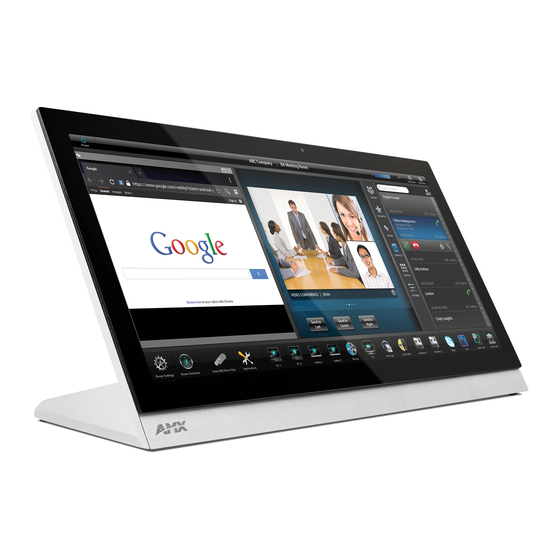
MXT-2001-PAN 20. 3" MODERO X SER IE S G5 PAN ORAMIC TABLETOP TOUCH PAN EL
MXD-2001-PAN-L 20.3" MODERO X SERI ES G5 PANORA MI C LANDSCAPE WALL MOUNT TOUCH PANEL
MXD-2001-PAN-P 20. 3" MODERO X SE RIE S G5 PA NORAMIC P ORTRAI T WALL MOUNT TOUCH P ANE L
MXT-1901-PAN 19. 4" MODER O X SERI ES G5 P ANOR AMI C TA BLETOP TOUCH PA NEL
MXD-1901-PAN-L 1 9.4 " MODERO X SER IE S G5 PAN ORAMIC LANDSCAPE WALL MOUNT TOUCH PANEL
MXD-1901-PAN-P 19.4" MODE RO X SERIES G5 PANORAMI C PORTRAIT WALL MOUN T TOUCH PANEL
MXT-1001 10.1" MODERO X SERI ES G5 TABLETOP TOUCH PANEL
MXD-1001-L 10 .1 " MODE RO X S ER IES G5 L ANDSCAPE WALL MOUNT TOUCH PANEL
MXD-1001-P 1 0. 1" MODER O X SERI ES G5 P ORTRAI T WALL MOUNT TOUCH P ANE L
MXT-701 7" MODERO X SERI ES G5 TABLETOP TOUCH PANEL
MXD-701-L 7 " MODE RO X S ER IES G5 L ANDSCAPE WALL MOUNT TOUCH PANEL
MXD-701-P 7" MODERO X SERI ES G5 PORTRAIT WALL MOUNT TOUCH PANEL
Advertisement
Table of Contents

Related Manuals for AMX MXT-2001-PAN


Summary of Contents for AMX MXT-2001-PAN
- Page 1 S E R I ES G 5 TO U CH PA N E L S MXT-2001-PAN 20. 3" MODERO X SER IE S G5 PAN ORAMIC TABLETOP TOUCH PAN EL MXD-2001-PAN-L 20.3" MODERO X SERI ES G5 PANORA MI C LANDSCAPE WALL MOUNT TOUCH PANEL MXD-2001-PAN-P 20.
-
Page 2: Copyright Notice
COPYRIGHT NOTICE AMX© 2015, all rights reserved. No part of this publication may be reproduced, stored in a retrieval system, or transmitted, in any form or by any means, electronic, mechanical, photocopying, recording, or otherwise, without the prior written permission of AMX. Copyright protection claimed... - Page 3 Anyone performing field maintenance on AMX equipment should use an appropriate ESD field service kit complete with at least a dissipative work mat with a ground cord and a UL listed adjustable wrist strap with another ground cord WARNING: Do Not Open! Risk of Electrical Shock.
- Page 4 WEEE (recast) Directive 2012/19/EU; European Union Radio and Telecommunications Terminal Equipment (R&TTE) Directive 1999/5/EC. You may obtain a free copy of the Declaration of Conformity by visiting http://www.amx.com/techcenter/certifications.asp. WEEE NOTICE: This appliance is labeled in accordance with European Directive 2012/19/EU concerning waste of electrical and electronic equipment (WEEE).
-
Page 5: Table Of Contents
MXD-701 (Wall-Mount - Landscape/Portrait)..............28 MXD-701 Specifications ........................28 Touch Panel Aspect Ratio ........................... 30 Installing Tabletop (MXT) Panels ..............31 MXT-2001-PAN / MXT-1901-PAN .................. 31 Connector Locations - MXT-2001-PAN / MXT-1901-PAN..............31 Modero X® Series G5 Touch Panels - Installation & Hardware Reference Manual... - Page 6 Table of Contents MXT-1001 / MXT-701 ..................... 32 Connector Locations - MXT-1001/MXT-701..................32 Power via 13.5V ............................32 Wiring a 13.5V Power Connection ........................32 Power via PoE ............................32 Ethernet Cable Installation and Modification..................... 33 Installing Wall-Mount (MXD) Panels ...............34 A Note About Wall and Rack Installation ...............
-
Page 7: Modero X Series G5 Touch Panels
FIG. 1 The Modero X Series G5 Touch Panels covered in this manual include: Modero X Series G5 Touch Panels Name Description Page Ref MXT-2001-PAN FG5968-35 20.3" Modero X Series G5 Panoramic Tabletop page 11 MXD-2001-PAN-P Portrait: FG5968-36 20.3" Modero X Series G5 Panoramic Wall-Mounts... -
Page 8: Sleep Button
Guide, available at www.amx.com. NOTE: Note: Programming the Modero X Series G5 touch panels require the use of the latest versions of NetLinx Studio and TPDesign5, both available to download at www.amx.com. Bluetooth Support X Series G5 touch panels allow the use of Bluetooth keyboard and mouse combinations, using HID Profile v1.1. Using a keyboard and mouse with the device requires use of the MXA-BT Bluetooth USB Adapter (FG5968-19). -
Page 9: Nfc Support
Modero X Series G5 Touch Panels NFC Support X Series G5 touch panels support Near Field Communications™ (NFC) Technology. NFC technology facilitates making transactions, exchanging digital content, and connecting electronic devices with a touch. NFC transmissions are short-range (from a touch to a few centimeters), working with existing contact-less card technologies and containing built-in capabilities to support secure applications. -
Page 10: Additional Documentation
NOTE: Refer to the Modero G5 Conf iguration and Programming - X Series G5 Touch Panels Instruction Manual for details. NOTE: Touch Panel f iles for G5 Touch Panels are created via TPDesign5 software (available to download from www.amx.com). Refer to the TPDesign5 online help and Instruction Manual for details. -
Page 11: Mxt/D-2001-Pan - 20.3" X Series G5 Panels
, 2.6A) • Standby: 7W (13.5V , 0.52A) EXTERNAL POWER Requires one of these AMX power sources (not included): SUPPLY REQUIRED • PSR4.4 Power Supply, 4.5A, 3.5mm Phoenix with Retention Screws (FG423-46) • PSN4.4 Power Supply, 4.5A, 3.5mm Phoenix, 13.5V (discontinued) (FG423-45) •... - Page 12 • File Formats: WAV, MP3 (as part of touch panel file only - no USB storage) • Intercom*: Full Duplex VoIP, SIP v2.0 GRAPHICS ENGINE AMX G5: G5 enhanced feature set supporting multi-touch and gestures, scrolling, transitions, applications - See TPD5 Operations Guide for more information EMBEDDED •...
-
Page 13: Mxd-2001-Pan (Wall-Mount - Landscape/Portrait)
, 2.6A) • Standby: 7 W (13.5V , 0.52A) EXTERNAL POWER Requires one of these AMX power sources (not included): SUPPLY REQUIRED • PSR4.4 Power Supply, 4.5A, 3.5mm Phoenix with Retention Screws (FG423-46) • PSN4.4 Power Supply, 4.5A, 3.5mm Phoenix, 13.5V (discontinued) (FG423-45) •... - Page 14 • File Formats: WAV, MP3 (as part of touch panel file only - no USB storage) • Intercom*: Full Duplex VoIP, SIP v2.0 GRAPHICS ENGINE AMX G5: G5 enhanced feature set supporting multi-touch and gestures, scrolling, transitions, applications - See TPD5 Operations Guide for more information EMBEDDED •...
- Page 15 MXT/D-2001-PAN - 20.3" X Series G5 Panels MXD-2001-PAN Specif ications (Cont.) CONNECTIONS • Ethernet: 10/100 port, RJ-45 connector • USB: (2) USB host 2.0, Type A ports (1) Micro-USB device port (currently not in use) • Power: 2-pin, locking 3.5mm Phoenix connector ENVIRONMENTAL •...
-
Page 16: Mxt/D-1901-Pan - 19.4" X Series G5 Panels
, 2.6A) • Standby: 7W (13.5V , 0.52A) EXTERNAL POWER Requires one of these AMX power sources (not included): SUPPLY REQUIRED • PSR4.4 Power Supply, 4.5A, 3.5mm Phoenix with Retention Screws (FG423-46) • PSN4.4 Power Supply, 4.5A, 3.5mm Phoenix, 13.5V (discontinued) (FG423-45) •... - Page 17 • File Formats: WAV, MP3 (as part of touch panel file only - no USB storage) • Intercom*: Full Duplex VoIP, SIP v2.0 GRAPHICS ENGINE AMX G5: G5 enhanced feature set supporting multi-touch and gestures, scrolling, transitions, applications - See TPD5 Operations Guide for more information EMBEDDED •...
-
Page 18: Mxd-1901-Pan (Wall-Mount - Landscape/Portrait)
, 2.6A) • Standby: 7 W (13.5V , 0.52A) EXTERNAL POWER Requires one of these AMX power sources (not included): SUPPLY REQUIRED • PSR4.4 Power Supply, 4.5A, 3.5mm Phoenix with Retention Screws (FG423-46) • PSN4.4 Power Supply, 4.5A, 3.5mm Phoenix, 13.5V (discontinued) (FG423-45) •... - Page 19 • File Formats: WAV, MP3 (as part of touch panel file only - no USB storage) • Intercom*: Full Duplex VoIP, SIP v2.0 GRAPHICS ENGINE AMX G5: G5 enhanced feature set supporting multi-touch and gestures, scrolling, transitions, applications - See TPD5 Operations Guide for more information EMBEDDED •...
- Page 20 MXT/D-1901-PAN - 19.4" X Series G5 Panels MXD-1901-PAN Specif ications (Cont.) CONNECTIONS • Ethernet: 10/100 port, RJ-45 connector • USB: (2) USB host 2.0, Type A ports (1) Micro-USB device port (currently not in use) • Power: 2-pin, locking 3.5mm Phoenix connector ENVIRONMENTAL •...
-
Page 21: Mxt/D-1001 - 10.1" X Series G5 Panels
• Shutdown: 1W • Start-Up Inrush Current: Not applicable due to PoE standard EXTERNAL POWER Optimal performance requires use of one of the following AMX PoE power supplies (not included): SUPPLY REQUIRED • PS-POE-AF-TC, PoE Injector, 802.3AF Compliant (FG423-83) • NXA-ENET8-2POE, Gigabit PoE Ethernet Switch (FG2178-63) CERTIFICATIONS •... - Page 22 • File Formats: WAV, MP3 (as part of touch panel file only - no USB storage) • Intercom*: Full Duplex VoIP, SIP v2.0 GRAPHICS ENGINE AMX G5: G5 enhanced feature set supporting multi-touch and gestures, scrolling, transitions, applications - See TPD5 Operations Guide for more information EMBEDDED •...
-
Page 23: Touch Panel Aspect Ratio
• Shutdown: 1W • Start-Up Inrush Current: Not applicable due to PoE standard EXTERNAL POWER Optimal performance requires use of one of the following AMX PoE power supplies (not included): SUPPLY REQUIRED • PS-POE-AF-TC, PoE Injector, 802.3AF Compliant (FG423-83) • NXA-ENET8-2POE, Gigabit PoE Ethernet Switch (FG2178-63) CERTIFICATIONS •... - Page 24 • File Formats: WAV, MP3 (as part of touch panel file only - no USB storage) • Intercom*: Full Duplex VoIP, SIP v2.0 GRAPHICS ENGINE AMX G5: G5 enhanced feature set supporting multi-touch and gestures, scrolling, transitions, applications - See TPD5 Operations Guide for more information EMBEDDED •...
-
Page 25: Touch Panel Aspect Ratio
MXT/D-1001 - 10.1" X Series G5 Panels MXD-1001 Specif ications (Cont.) CONNECTIONS • Ethernet: 10/100 port, RJ-45 connector through cable extension • USB: (2) USB host 2.0, Type A ports (1) Micro-USB device port (currently not in use) • Power: PoE (Power over Ethernet), 802.3af, class 3 ENVIRONMENTAL •... -
Page 26: Mxt/D-701 - 7" X Series G5 Panels
• Shutdown: 1W • Start-Up Inrush Current: Not applicable due to PoE standard EXTERNAL POWER Optimal performance requires use of one of the following AMX PoE power supplies (not included): SUPPLY REQUIRED: • PS-POE-AF-TC, PoE Injector, 802.3AF Compliant (FG423-83) • NXA-ENET8-2POE, Gigabit PoE Ethernet Switch (FG2178-63) CERTIFICATIONS •... -
Page 27: Touch Panel Aspect Ratio
• File Formats: WAV, MP3 (as part of touch panel file only - no USB storage) • Intercom*: Full Duplex VoIP, SIP v2.0 GRAPHICS ENGINE AMX G5: G5 enhanced feature set supporting multi-touch and gestures, scrolling, transitions, applications - See TPD5 Operations Guide for more information EMBEDDED •... -
Page 28: Mxd-701 (Wall-Mount - Landscape/Portrait)
• Shutdown: 1 W • Start-Up Inrush Current: Not applicable due to PoE standard EXTERNAL POWER Optimal performance requires use of one of the following AMX PoE power supplies (not included): SUPPLY REQUIRED • PS-POE-AF-TC, PoE Injector, 802.3AF Compliant (FG423-83) •... - Page 29 • File Formats: WAV, MP3 (as part of touch panel file only - no USB storage) • Intercom*: Full Duplex VoIP, SIP v2.0 GRAPHICS ENGINE AMX G5: G5 enhanced feature set supporting multi-touch and gestures, scrolling, transitions, applications - See TPD5 Operations Guide for more information EMBEDDED •...
-
Page 30: Touch Panel Aspect Ratio
MXT/D-701 - 7" X Series G5 Panels MXD-701 Specif ications (Cont.) ENVIRONMENTAL • Temperature (Operating): 32°F to 104°F (0°C to 40°C) • Temperature (Storage): 4°F to 140°F (-20°C to 60°C) • Humidity (Operating): 20% to 85% RH • Humidity (Storage): 5% to 85% RH •... -
Page 31: Installing Tabletop (Mxt) Panels
The underside USB port, as well as the two rear USB ports, may be used with a flash drive for page transfers or firmware upgrades. The MXT-2001-PAN and MXT-1901-PAN have a slot at the base with channels for securing power and Ethernet cables, to allow options for cable configuration (FIG. -
Page 32: Mxt-1001 / Mxt-701
Power for the MXT-1001 and MXT-701 is supplied via PoE (Power Over Ethernet), utilizing an AMX-certified, capacitive touch- compliant PoE injector such as the PS-POE-AT High Power PoE Injector (FG423-81) or other approved AMX PoE power source. The incoming Ethernet cable should be connected to the RJ45 port on the cable attached to the device. -
Page 33: Ethernet Cable Installation And Modification
Installing Tabletop (MXT) Panels Ethernet Cable Installation and Modif ication In tabletop installations where concealing the Ethernet cable is desired, a hole at least 1.00” (2.54 cm) in diameter is required in the surface to allow passage of the female RJ45 connector (FIG. 19). If using a smaller hole is unavoidable, you will need to disconnect the Ethernet cable (ECA5968-05) from the device, to feed the male end of the cable through. -
Page 34: Installing Wall-Mount (Mxd) Panels
FIG. 20 shows an AMX device installed in a wall with a filled volume (such as with insulation or concrete), as well as with a closed volume (such as between studs in an otherwise finished wall). The diagram shows how heat generated by the device or other devices may have no way to escape, and may build up to levels that may affect device operation. -
Page 35: Installation Recommendations
The Backbox has four locking tabs (two on top and two on bottom) to lock the Backbox to the wall (FIG. 23). Note that FIG. 23 shows the MXD-1901-PAN, but the locking tabs are in a similar location on the MXT-2001-PAN. -
Page 36: Mxd-2001-Pan Dimensions
FIG. 24 provides dimensions for the MXD-2001-PAN: Notes: Dimensions in parenthesis are in millimeters Additional detailed installation and product drawings are available to view/download at www.amx.com MXD-2001-PAN - Dimensions FIG. 24 Modero X® Series G5 Touch Panels - Installation & Hardware Reference Manual... -
Page 37: Mxd-1901-Pan Dimensions
FIG. 25 provides dimensions for the MXD-1901-PAN: Notes: Dimensions in parenthesis are in millimeters Additional detailed installation and product drawings are available to view/download at www.amx.com MXD-1901-PAN - Dimensions FIG. 25 NOTE: In order to ensure a stable installation, the thickness of the wall material must be a minimum of .50 inches (1.27cm) and a maximum of .875 inches (2.22cm). -
Page 38: Installing The Backbox
Portrait panels, except for the vertical orientation. Additional detailed installation and product drawings (for both Landscape and Portrait panels) are available to view/download at www.amx.com MXD-2001-PAN-L Installation Dimensions (side view) FIG. 27 Modero X® Series G5 Touch Panels - Installation & Hardware Reference Manual... -
Page 39: Mxd-1901-Pan Installation Dimensions
Portrait panels, except for the vertical orientation. Additional detailed installation and product drawings (for both Landscape and Portrait panels) are available to view/download at www.amx.com MXD-1901-PAN-L Installation Dimensions (side view) FIG. 29 Since the cutout for the Backbox is off-center from the edges of the touch panel, use the included Installation Template to ensure proper placement. - Page 40 Routing As Needed placement (optional) Note: Additional detailed installation and product drawings are available to view/download at www.amx.com MXD-1901-PAN Backbox installation (Landscape) FIG. 30 Remove any knockouts as needed on either long dimension of the Backbox to facilitate incoming wiring and pull the wiring through the resultant holes.
-
Page 41: Power Via 13.5V
6X 4-40 X 1/4" LONG FLAT HEAD TORQUE TO 5±.2 IN LBS Note: Additional detailed installation and product drawings are available to view/download at www.amx.com MXD-1901-PAN installation (Landscape) FIG. 32 NOTE: When installing the panel, do NOT press on or near the center of the panel. Too much stress at the center may damage the touch screen surface. -
Page 42: Wiring A 13.5V Power Connection
To reattach the panel to its Backbox, repeat the installation procedure. NOTE: For further information, refer to the video available at www.amx.com (go to Newsroom > Videos > Touch Panels). Modero X® Series G5 Touch Panels - Installation & Hardware Reference Manual... -
Page 43: Mxd-1001 / Mxd-701 Installation
MXD-1001 MXD-701 are available to download from www.amx.com. MXD-1001 and MXD-701panels may be installed directly into a solid surface, using either solid surface screws or the included locking tabs for different mounting options. Once installed, the panel is contained within a clear outer housing known as the Backbox (FIG. 35). This Backbox is removed to install the device into a wall or when using the optional Rough-In Box accessory (FG039-17). -
Page 44: Mxd-1001 Dimensions
FIG. 37 provides dimensions for the MXD-1001: Notes: Dimensions in parenthesis are in millimeters Additional detailed installation and product drawings are available to view/download at www.amx.com MXD-1001 - Dimensions FIG. 37 Modero X® Series G5 Touch Panels - Installation & Hardware Reference Manual... -
Page 45: Mxd-701 Dimensions
FIG. 37 provides dimensions for the MXD-701: Notes: Dimensions in parenthesis are in millimeters Additional detailed installation and product drawings are available to view/download at www.amx.com MXD-701 - Dimensions FIG. 38 NOTE: In order to ensure a stable installation, the thickness of the wall material must be a minimum of .50 inches (1.27cm) and a maximum of .875 inches (2.22cm). -
Page 46: Installing The Backbox
Portrait panels, except for the vertical orientation. Additional detailed installation and product drawings (for both Landscape and Portrait panels) are available to view/download at www.amx.com MXD-1001 Installation Dimensions (side view) FIG. 40 Modero X® Series G5 Touch Panels - Installation & Hardware Reference Manual... -
Page 47: Mxd-701 Installation Dimensions
Portrait panels, except for the vertical orientation. Additional detailed installation and product drawings (for both Landscape and Portrait panels) are available to view/download at www.amx.com MXD-701 Installation Dimensions (side view) FIG. 42 Use the included Installation Template to ensure proper placement. - Page 48 4X Knock-Outs Remove for Cable Routing as Needed #4 Screws Note: Additional detailed installation and product drawings are available to view/download at www.amx.com MXD-1001 Backbox Installation (Landscape) FIG. 43 Modero X® Series G5 Touch Panels - Installation & Hardware Reference Manual...
- Page 49 Routing as Needed #4 Screws Note: Additional detailed installation and product drawings are available to view/download at www.amx.com MXD-701 Backbox Installation (Landscape) FIG. 44 Remove any knockouts as needed on either long dimension of the Backbox to facilitate incoming wiring and pull the wiring through the resultant holes.
-
Page 50: Power Via Poe
Power via PoE Power for the MXD-1001 and MXD-701 is supplied via PoE (Power Over Ethernet ), utilizing an AMX-certified, capacitive touch- compliant PoE injector such as the PS-POE-AT High Power PoE Injector (FG423-81) or other approved AMX PoE power source. -
Page 51: Uninstalling The Mxd-1001
To reattach the panel to its Backbox, repeat the installation procedure. NOTE: For further information, refer to the video available at www.amx.com (go to Newsroom > Videos > Touch Panels). Modero X® Series G5 Touch Panels - Installation & Hardware Reference Manual... -
Page 52: Uninstalling The Mxd-701
To reattach the panel to its Backbox, repeat the installation procedure. NOTE: For further information, refer to the video available at www.amx.com (go to Newsroom > Videos > Touch Panels). Modero X® Series G5 Touch Panels - Installation & Hardware Reference Manual... -
Page 53: Appendix: Troubleshooting
Appendix: Troubleshooting Appendix: Troubleshooting Overview This section describes the solutions to possible hardware/firmware issues that could arise during the common operation of a Modero X Series G5 touch panel. Panel Doesn’t Respond To Touches Symptom: The device either does not respond to touches on the touch screen or does not register the touch as being in the correct area of the screen. - Page 54 © 2015 Harman. All rights reserved. Modero X and Modero X Series, AMX, AV FOR AN IT WORLD, HARMAN, and their respective logos are registered Last Revised: trademarks of HARMAN. Oracle, Java and any other company or brand name referenced may be trademarks/registered trademarks of their respective 12/16/2015 companies.
Need help?
Do you have a question about the MXT-2001-PAN and is the answer not in the manual?
Questions and answers