AMX MXT-2000XL-PAN Operation/Reference Manual
20.3" modero x series panoramic touch panel
Hide thumbs
Also See for MXT-2000XL-PAN:
- Installation manual (2 pages) ,
- Quick start manuals (2 pages)

Related Manuals for AMX MXT-2000XL-PAN


Summary of Contents for AMX MXT-2000XL-PAN
- Page 1 Operation/Reference Guide MXT/D-2000XL-PAN 20.3" Modero X Series® Panoramic Tabletop Touch Panel 20.3" Modero X Series® Panoramic Wall Touch Panel Touch Panels L a s t U p d a t e d : 1 0 / 2 4 / 2 0 1 2...
- Page 2 AMX is not responsible for products returned without a valid RMA number. AMX is not liable for any damages caused by its products or for the failure of its products to perform. This includes any lost profits, lost savings, incidental damages, or consequential damages.
- Page 3 LICENSE GRANT. AMX grants to Licensee the non-exclusive right to use the AMX Software in the manner described in this License. The AMX Software is licensed, not sold. This license does not grant Licensee the right to create derivative works of the AMX Software.
-
Page 5: Table Of Contents
Modero X Dealer Benefits ..................1 Modero X Customer Benefits ................... 1 MXT-2000XL-PAN..................... 2 Connector Locations ....................5 Memory........................... 5 Basic Operation....................... 5 Powering on the MXT-2000XL-PAN ................5 Microphone ........................5 Audio/Video Capabilities ....................5 MXT-2000XL-PAN-NC ..................... 5 MXD-2000XL-PAN ....................6 Memory........................... 8 Basic Operation....................... - Page 6 Table of Contents Configuration and Programming ..............25 Modero X Series Programming Guide ..............25 Upgrading Firmware ..................27 Overview ........................ 27 Upgrading Firmware via USB Flash Drive ............... 27 Load the Firmware on a USB Flash Drive ..............27 Transfer the Firmware File From the Flash Drive to the Touch Panel......28 Upgrading from Previous Firmware ................
-
Page 7: Modero X Series Touch Panels
Modero X Series® Touch Panels ® Modero X Series Touch Panels Overview See more and do more with the most elegant interface designed specifically for dedicated room control. The ® Modero X Series Touch Panels provide several industry firsts, including a beautiful, panoramic capacitive multi-touch screen that provides users access to multiple applications with minimal navigation. -
Page 8: Mxt-2000Xl-Pan
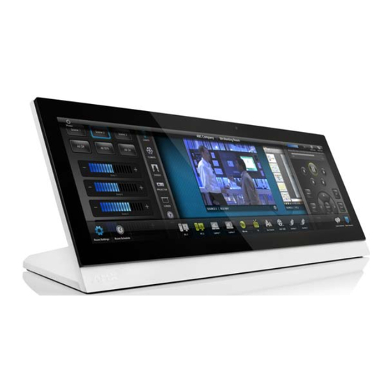
FIG. 1 MXT-2000XL-PAN touch panel The MXT-2000XL-PAN features a 20.4" x 9.5" (519 mm x 242 mm), 21.3" (541 mm) diagonal display, with a viewable area of 18.7" x 7.8" (475 mm x 198 mm), 20.3" (514 mm). The device communicates via Ethernet (10/100 port, RJ-45 connector, supported IP and IP-based protocols: UCP, TCP, ICMP, ICSP, IGMP, DHCP, Telnet, FTP, DNS, RFB for VNC, and HTTP) and USB (3 USB host 2.0, Type A ports and 1 Micro-USB device port). - Page 9 Modero X Series® Touch Panels MXT-2000XL-PAN Specifications Power Requirements: 12VDC, 4.4A: 2-pin, locking 3.5mm captive wire connector Power Consumption: • Constant current: 2.7A (32W) @ 12VDC • Start up current: 4.05A (48W) @ 12VDC • Standby current: 0.3A (3.1W) @ 12VDC •...
- Page 10 Streaming/File Formats: WAV, MP3 Intercom: Full Duplex VoIP, SIP v2.0 (supported with AMX-CSG) Operating Environment: • Operating Temperature: 32° F to 104° F (0° C to 40° C) • Storage Temperature: 4° F to 140° F (-20° C to 60° C) •...
-
Page 11: Connector Locations
Memory The MXT-2000XL-PAN comes with 512 MB of SDRAM and 4 GB of Flash memory, neither of which can be upgraded. A maximum of 2.4 GB is available to the user for projects. Basic Operation The MXT-2000XL-PAN is operated using its integral touchscreen, as well as the Sleep button on the top of the device (FIG. -
Page 12: Mxd-2000Xl-Pan
Modero X Series® Touch Panels MXD-2000XL-PAN The MXD-2000XL-PAN 19.4” Modero X Series Panoramic Wall Touch Panels (Portrait Wall Mount: FG5968-05; Landscape Wall Mount: FG5968-11) are ideal for boardrooms, conference rooms, or auditoriums where a panoramic control surface is needed to provide access to multiple functions simultaneously while remaining elegantly unobtrusive. - Page 13 Modero X Series® Touch Panels MXD-2000XL-PAN Specifications Power Requirements: 12VDC, 4.4A: 2-pin, locking 3.5mm captive wire connector Power Consumption: • Constant current: 2.7A (32W) @ 12VDC • Start up current: 4.05A (48W) @ 12VDC • Standby current: 0.3A (3.1W) @ 12VDC •...
-
Page 14: Memory
Audio: Streaming/File Formats: WAV, MP3 Intercom: Full Duplex VoIP, SIP v2.0 (supported with AMX-CSG) Operating • Operating Temperature: 32° F to 104° F (0° C to 40° C) Environment: • Storage Temperature: 4° F to 140° F (-20° C to 60° C) •... -
Page 15: Mxd-2000Xl-Pan-Nc
Modero X Series® Touch Panels MXD-2000XL-PAN-NC The MXD-2000XL-PAN-P-NC (FG5968-33) and MXD-2000XL-PAN-L-NC (FG5968-34) No Comm touch panels do not have camera, microphone, or NFC capability. These otherwise have all of the functionality of the MXD-2000XL-PAN panels. MXD/T-2000XL-PAN 20.3" Modero X Series® Panoramic Touch Panels... -
Page 16: Mxd/T-2000Xl-Pan Features
Picture View may be stopped at any time by removing the USB drive, and the MXT-2000XL-PAN will return to its default display page. -
Page 17: Preview Mode And Normal Mode
Touching any place on the display will result in the configuration popup to slide from the bottom of the display. Picture View goes into its Normal Mode when the MXT-2000XL-PAN goes into idle timeout while connected to a USB drive. Normal Mode displays images until the touchscreen is touched, or some other wakeup event is detected. -
Page 18: Picture View Send Command
The antenna itself is accessible from the front of the panel, 3.25" (82.55 mm) from the left corner of the panel and 0.375" (9.53 mm) from the top edge. When using an NFC device with the MXT-2000XL-PAN, you should align your device’s antenna with the center of the touch panel’s antenna (FIG. 8). -
Page 19: Cleaning The Touch Overlay And Case
Cleaning the Touch Overlay and Case Both the MXT-2000XL-PAN and the MXD-2000XL-PAN come with the MXA-CLK Modero X Series Cleaning Kit (FG5968-16), which may be used to clean fingerprints and dirt from the device. This kit comes with cleaning cloths and a bottle of cleaning fluid specifically for use with the device. - Page 20 Modero X Series® Touch Panels MXD/T-2000XL-PAN 20.3" Modero X Series® Panoramic Touch Panels...
-
Page 21: Installation
MXT-2000XL-PAN underside connectors The MXT-2000XL-PAN does not have individual channels on the base of the device to allow passage of cables from underneath the base. Instead, it has one slot at the base to allow options on cable configuration, with channels for securing power, Ethernet, and Micro-USB cables (FIG. -
Page 22: Wiring A Power Connection
Installation Connecting power to the MXT-2000XL-PAN should be done using the included 2-pin 3.5mm captive wire connector included with the device. This connector is retained within its port with locking screws instead of the pins on each side of standard captive wire connectors, and using force to insert a standard captive wire connector may damage the device. -
Page 23: A Note About Wall And Rack Installation
FIG. 12 shows an AMX device installed in a wall with a filled volume (such as with insulation or concrete), as well as with a closed volume (such as between studs in an otherwise finished wall). The diagram shows how heat generated by the device or other devices may have no way to escape, and may build up to levels that may affect device operation. -
Page 24: Installation Recommendations
Installation Installation Recommendations During any installation, a lack of ventilation may produce conditions that may adversely affect the device’s operation. In these circumstances, special care must be made to make sure that temperatures within enclosed areas do not exceed the device’s maximum rated temperature. While the outside temperature of the device may be at or below its maximum operating temperature, special care must be taken before and during installation to ensure that the maximum operating temperature is not exceeded within wall or rack... - Page 25 Installation Wall Back Box MXD-2000XL-PAN Temporary Mounting Posts (front) Back box knockouts FIG. 15 Side view of installed MXD-2000XL-PAN (Landscape) Wall MXD-2000XL-PAN Back box Locking tabs (front) knockouts FIG. 16 Side view of installed MXD-2000XL-PAN (Portrait) In order to guarantee a stable installation of the MXD-2000XL-PAN, the thickness of the wall material must be a minimum of .50 inches (1.27cm) and a maximum of .875 inches (2.22cm).
- Page 26 Installation The maximum recommended torque to screw in the locking tabs on the plastic back box is 5 IN-LB [56 N-CM]. Applying excessive torque while tightening the tab screws, such as with powered screwdrivers, can strip out the locking tabs or damage the plastic back box.
- Page 27 Installation Cables routed to wall opening Outer edge of back box Back box cutout Knockouts top) Locking tab Mounting screw placement (optional) FIG. 18 MXD-2000XL-PAN Back Box installation (Landscape) Outer edge of back box Back box cutout Cables routed to wall opening Knockouts Locking tab Mounting screw...
- Page 28 Installation Extend the locking tabs on the sides of the back box by tightening the screws inside the box until snug. Not all of the tabs must be extended to lock the back box in place, but extending a minimum of the top and bottom tabs is highly recommended.
- Page 29 Installation Wall Mounting post openings Mounting Side cover posts FIG. 21 MXD-2000XL-PAN installation (Landscape) Side cover Screws Wall Mounting post openings Side cover Screws FIG. 22 MXD-2000XL-PAN installation (Portrait) MXD/T-2000XL-PAN 20.3" Modero X Series® Panoramic Touch Panels...
-
Page 30: Wiring A Power Connection
Installation When installing the panel, do NOT press on or near the center of the panel. Too much stress at the center may damage the touch screen surface. When installing the panel, pressure should be applied toward the ends of the panel ONLY. Use the six provided screws, three at each end, to secure the touch panel to the back box (FIG. -
Page 31: Configuration And Programming
Configuration and Programming Programming the MXT-2000XL-PAN and MXD-2000XL-PAN require the use of the latest versions of NetLinx Studio and TPDesign 4, both available at www.amx.com. Modero X Series Programming Guide Information on Settings pages, panel configuration, and programming is included in the Modero X Series Programming Guide, available at www.amx.com. - Page 32 Configuration and Programming MXD/T-2000XL-PAN 20.3" Modero X Series® Panoramic Touch Panels...
-
Page 33: Upgrading Firmware
Firmware and TPDesign4 files may be transferred to the panel made via USB flash drive. When looking at the device from the front, the MXT-2000XL-PAN has two USB ports on the rear right of the device (FIG. 3) and one USB port on the underside (FIG. 9). -
Page 34: Transfer The Firmware File From The Flash Drive To The Touch Panel
Upgrading Firmware Make sure this is the only .kit file in this directory - if not, the latest version will be used. Eject or unmount the flash drive from the PC. Transfer the Firmware File From the Flash Drive to the Touch Panel Connect the USB Flash Drive to one of the USB Type A ports on the panel. -
Page 35: Upgrading From Previous Firmware
If you choose Yes, the device will retrieve the files and then reboot. Returning to Factory Default Firmware The MXT-2000XL-PAN and MXD-2000XL-PAN allow the option to return the device to its original factory default firmware, which may be necessary in certain situations. To return the device to its factory default firmware: From the Settings page, select the Configuration page. -
Page 36: Upgrading Firmware Via Netlinx Studio
Upgrading Firmware Upgrading Firmware Via NetLinx Studio The MXT-2000XL-PAN and MXD-2000XL-PAN use an Ethernet connection for programming, firmware updates, and touch panel file transfer via NetLinx Studio. If you have access to the panel’s network, you may transfer files directly to the panel through NetLinx Studio Firmware upgrades cannot be made through an Ethernet-connected PC to the touch panel, unless that PC is connected to the panel’s network. - Page 37 Upgrading Firmware FIG. 31 Virtual NetLinx Master Settings Within this dialog, enter the Master System number. The default is 1. In the Available Connections section, click on the IP address for the touch panel to select it. In the Virtual NetLinx Master Settings dialog box, click OK to close the box. In the Communications Settings dialog box, click OK to close the box.
-
Page 38: Viewing Devices On The Virtual System
The panel-specific firmware is shown on the right of the listed panel. Download the latest firmware file from www.amx.com and then save the Kit file to your computer. Note that each Kit file is intended for download to its corresponding panel. - Page 39 System list with devices on your particular system. Confirm that the panel has been properly updated to the correct firmware version. Verify you have downloaded the latest firmware file from www.amx.com and then save the Kit file to your computer.
- Page 40 Upgrading Firmware MXD/T-2000XL-PAN 20.3" Modero X Series® Panoramic Touch Panels...
-
Page 41: Appendix: Troubleshooting
Appendix: Troubleshooting Appendix: Troubleshooting Overview This section describes the solutions to possible hardware/firmware issues that could arise during the common operation of a Modero X touch panel. Panel Doesn’t Respond To Touches Symptom: The device either does not respond to touches on the touch screen or does not register the touch as being in the correct area of the screen. - Page 42 Appendix: Troubleshooting MXD/T-2000XL-PAN 20.3" Modero X Series® Panoramic Touch Panels...
- Page 43 Appendix B - Troubleshooting MXD/T-2000XL-PAN 20.3" Modero X Series® Panoramic Touch Panels...
- Page 44 It’s Your World - Take Control™ 3000 RESEARCH DRIVE, RICHARDSON, TX 75082 USA • 800.222.0193 • 469.624.8000 • 469-624-7153 fax • 800.932.6993 technical support • www.amx.com...
Need help?
Do you have a question about the MXT-2000XL-PAN and is the answer not in the manual?
Questions and answers