Table of Contents

Subscribe to Our Youtube Channel
Related Manuals for AMX D-1901-PAN


Summary of Contents for AMX D-1901-PAN
- Page 1 O p e r a t i o n / R e f e r e n c e G u i d e MXT/D-1901-PAN 19.4" Modero X Series® G5 Panoramic Tabletop Touch Panel 19.4" Modero X Series® G5 Panoramic Wall Touch Panel...
- Page 2 AMX is not responsible for products returned without a valid RMA number. AMX is not liable for any damages caused by its products or for the failure of its products to perform. This includes any lost profits, lost savings, incidental damages, or consequential damages.
-
Page 3: Table Of Contents
Table of Contents Table of Contents Modero X Series® G5 Touch Panels ..............1 Overview ........................1 Features ........................1 Modero X Dealer Benefits ..................1 Modero X Customer Benefits ................... 1 MXT-1901-PAN ......................2 Connector Locations......................5 Memory ........................... 5 Basic Operation ....................... - Page 4 Table of Contents Transfer the Firmware File From the Flash Drive to the Touch Panel......23 Removing All Data From The Touch Panel ..............24 Resetting the Touch Panel Settings to Factory Defaults ..........24 Resetting to Factory-Installed Firmware................ 25 Installing Previous Firmware..................
-
Page 5: Modero X Series G5 Touch Panels
Modero X Series® G5 Touch Panels ® Modero X Series G5 Touch Panels Overview The most elegant interface designed specifically for dedicated room control has been significantly enhanced to include a new G5 Graphic Engine to provide even faster and smoother animations and transitions, and we quadrupled the processing power with a new Quad Core Processor. -
Page 6: Mxt-1901-Pan
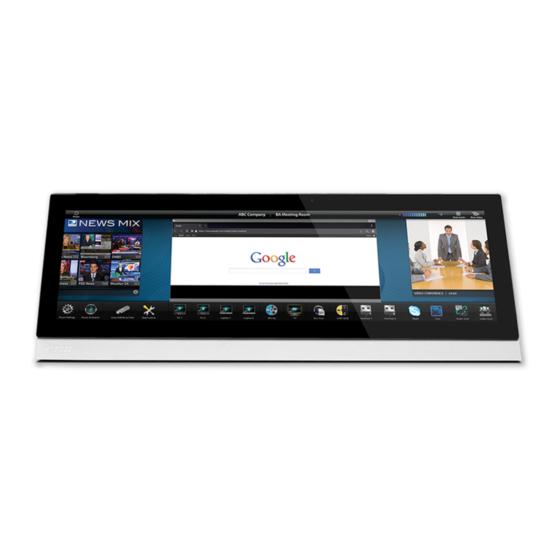
Modero X Series® G5 Touch Panels MXT-1901-PAN The MXT-1901-PAN (FG5968-41) (FIG. 1) is ideal for boardrooms, conference rooms, or auditoriums where a panoramic control surface is needed to provide access to multiple functions simultaneously while remaining elegantly unobtrusive. In residences, it is perfect for kitchens, home theaters, or home offices where the panoramic control surface can be used to manage systems throughout the house. - Page 7 Modero X Series® G5 Touch Panels MXT-1901-PAN Specifications Power Requirements: 12VDC, 4.4A LPS: 2-pin, locking 3.5mm captive wire connector. Power Consumption: • Full-On: 35 W (12 VDC, 2.9 A) • Standby: 7 W (12 VDC, 0.6 A) • Recommended minimum power supply: 4.4A (PSN4.4) Front Panel Components: NFC Transceiver: Antenna and transceiver for Near Field Communications device detection and interaction.
- Page 8 • HPG-10 .75-inch HydraPort .75-IN. Grommet (FG570-01) • Type A USB Covers (2) • Tie Wrap for Power Source Ferrite Other AMX Equipment: • MXA-MP, Modero X/S Series Multi Preview (FG5968-20) • MXA-MPL, Modero X/S Series Multi Preview Live (FG5968-10) •...
-
Page 9: Connector Locations
Modero X Series® G5 Touch Panels Connector Locations With the unit facing you, the two USB ports for peripherals are located on the rear right corner of the device (FIG. 3). The power and Ethernet connectors, as well as an additional USB port are located on the bottom of the device. Type A USB Ports FIG. -
Page 10: Mxd-1901-Pan
Modero X Series® G5 Touch Panels MXD-1901-PAN The MXD-1901-PAN 19.4” Modero X Series G5 Panoramic Wall Touch Panels (Portrait Wall Mount: FG5968-42; Landscape Wall Mount: FG5968-43) are ideal for boardrooms, conference rooms, or auditoriums where a panoramic control surface is needed to provide access to multiple functions simultaneously while remaining elegantly unobtrusive. In residences, they are perfect for kitchens, home theaters, or home offices where the panoramic control surface can be used to manage systems throughout the house. - Page 11 Modero X Series® G5 Touch Panels MXD-1901-PAN Specifications Power Requirements: 12VDC, 4.4A LPS: 2-pin, locking 3.5mm captive wire connector. Power Consumption: • Full-On: 35 W (12 VDC, 2.9 A) • Standby: 7 W (12 VDC, 0.6 A) • Recommended minimum power supply: 4.4A (PSN4.4) Front Panel Components: NFC Transceiver: Antenna and transceiver for Near Field Communications device detection and interaction.
- Page 12 • MXA-CLK Modero X Series Cleaning Kit (FG5968-16) • 3.5mm Locking Captive Wire Connector (41-0002-SA) • MXD-1901-PAN Back Box (68-5968-02) Other AMX Equipment • MXA-MP, Modero X/S Series Multi Preview (FG5968-20) • MXA-MPL, Modero X/S Series Multi Preview Live (FG5968-10) •...
-
Page 13: Memory
For more information on connecting and configuring the touch panels to a network, please refer to the Modero X Series G5 Programming Guide, available at www.amx.com. Both the MXT-1901-PAN and the MXD-1901-PAN support Near Field Communications™ (NFC) Technology. NFC technology facilitates making transactions, exchanging digital content, and connecting electronic devices with a touch. -
Page 14: Cleaning The Touch Overlay And Case
Modero X Series® G5 Touch Panels NFC antenna location 3.25" (82.55 mm) 0.375" (9.53 mm) FIG. 6 NFC antenna location on the MXT-1901-PAN To facilitate NFC antenna access, you may want to add an icon to the panel’s page(s), pointing to the location of the antenna on the panel. Cleaning the Touch Overlay and Case Both the MXT-1901-PAN and the MXD-1901-PAN come with the MXA-CLK Modero X Series Cleaning Kit (FG5968- 16), which may be used to clean fingerprints and dirt from the device. -
Page 15: Installation
Installation Installation MXT-1901-PAN Installation Other than the two USB ports on the back of the device (FIG. 3), the power and data connectors for the MXT-1901-PAN are located on the underside of the device (FIG. 7). The underside USB port, as well as the two rear USB ports, may be used with a flash drive for page transfers or firmware upgrades. -
Page 16: Wiring A Power Connection
FIG. 10 shows an AMX device installed in a wall with a filled volume (such as with insulation or concrete), as well as with a closed volume (such as between studs in an otherwise finished wall). The diagram shows how heat generated by the device or other devices may have no way to escape, and may build up to levels that may affect device operation. -
Page 17: Installation Recommendations
Installation In FIG. 11, the diagram displays an AMX device in a typical rack mounting, with full air circulation around the front and back of the device. In this case, the main concern is with heat building up between components, possibly to levels that may affect device operation. -
Page 18: Mxd-1901-Pan Installation
Installation MXD-1901-PAN Installation The MXD-1901-PAN may be installed directly into a solid surface environment, using either solid surface screws or the included locking tabs for different mounting options. Once installed, the MXD-1901-PAN is contained within a clear outer housing known as the back box. This back box is removed when installing the device into a wall or when using the optional Rough-In Box accessory (FG039-15). - Page 19 Installation Wall MXD-1901-PAN Back box Locking tabs front) knockouts FIG. 14 Side view of installed MXD-1901-PAN (Portrait) In order to guarantee a stable installation of the MXD-1901-PAN, the thickness of the wall material must be a minimum of .50 inches (1.27cm) and a maximum of .875 inches (2.22cm).
- Page 20 Installation 20.433" 519.00 mm) 14.50" 368.30 mm) 6.89" 175.00 mm) 5.69" 144.50 mm) FIG. 15 MXD-1901-PAN Template Using the included template to select the final placement of the back box is highly recommended. The outside edges of the template are the same dimensions as the touch panel, which allows you to troubleshoot possible conflicts with wall edges, doors, and other potential obstacles.
- Page 21 Installation Outer edge of back box Back box cutout Cables routed to wall opening Knockouts Locking tab Mounting screw placement (optional) FIG. 17 MXD-1901-PAN Back Box installation (Portrait) Remove any knockouts as needed on either long dimension of the back box (FIG. 16 and FIG. 17) to facilitate incoming wiring and pull the wiring through the resultant holes.
- Page 22 Installation 12 VDC USB Port Power Port Ethernet 10/100 Port Limited Access USB Port FIG. 18 MXD-1901-PAN rear connectors (front view) Test the incoming wiring by attaching the panel connections to their terminal locations and applying power. Verify that the panel is receiving power and functioning properly to prevent repetition of the installation. Do not disconnect the connectors from the touch panel.
- Page 23 Installation Side cover Screws Wall Mounting post openings Screws Side cover FIG. 20 MXD-1901-PAN installation (Portrait) When installing the panel, do NOT press on or near the center of the panel. Too much stress at the center may damage the touch screen surface. When installing the panel, pressure should be applied toward the ends of the panel ONLY.
-
Page 24: Wiring A Power Connection
Installation Screws (3) MXD-1901-PAN Side cover FIG. 21 MXD-1901-PAN side cover installation (Landscape) Snap the decorative side covers (FIG. 21) onto each end of the touch panel. Reconnect the terminal Ethernet and USB to their respective locations on the Ethernet port. Wiring a Power Connection To use the 2-pin 3.5 mm captive wire connector with a 12 VDC-compliant power supply, the incoming PWR and GND wires from the external source must be connected to their corresponding locations on the connector (FIG. -
Page 25: Configuration And Programming
Configuration and Programming Programming the MXT-1901-PAN and MXD-1901-PAN require the use of the latest versions of NetLinx Studio and TPDesign5, both available at www.amx.com. Modero X Series G5 Programming Guide Information on the Settings app, panel configuration, and programming is included in the Modero X Series G5 Programming Guide, available at www.amx.com. - Page 26 Configuration and Programming MXD/T-1901-PAN 19.4" Modero X Series® G5 Touch Panels...
-
Page 27: Upgrading Firmware
Overview The latest firmware (*.kit) file for each panel is available to download from www.amx.com. To download firmware files, go to the catalog page for your panel type, and click the link under "Firmware Files" on the right side of the catalog page. -
Page 28: Removing All Data From The Touch Panel
Upgrading Firmware Removing All Data From The Touch Panel To reset the touch panel to its factory defaults and remove all data stored in the device: From the Reset & Update menu, select Factory Data Reset to open the Factory Data Reset window (FIG. 24). FIG. -
Page 29: Resetting To Factory-Installed Firmware
Upgrading Firmware Resetting to Factory-Installed Firmware In certain circumstances, it may be necessary to uninstall the current firmware on a touch panel and return the panel to its original factory default firmware. To reset the touch panel to its original factory firmware: From the Reset and Update menu, select Update Firmware to open the Firmware Update window (FIG. -
Page 30: Installing New Firmware From An External Usb Stick
To install new firmware to the touch panel from an external disk via the Settings app: Download the latest Modero X Series G5 touch panel firmware from www.amx.com and save it to a USB stick or other external drive with USB capability. -
Page 31: Installing Touch Panel Pages From An External Disk
Upgrading Firmware Installing Touch Panel Pages From An External Disk TPDesign5 page files may be loaded onto a touch panel, both via TPDesign5 and through files saved to a USB-enabled external drive.To load TPD5 pages via USB: Download the panel pages and save them to a USB stick or other external drive with USB capability. Insert the USB stick into an available USB port. - Page 32 Upgrading Firmware When NetLinx Studio detects that the file is a G5 *.kit file, it will automatically attempt to send the file via HTTP (using the stand-alone web server that is started by NetLinx Studio). The steps for initiating a firmware transfer to a G5 touch panel are essentially the same as for any other NetLinx device.
- Page 33 Upgrading Firmware FIG. 34 NetLinx Studio v3.4 or higher - HTTP Server Error dialog In this case, there are two options for proceeding with the firmware transfer: Select Transfer the KIT File via the NetLinx Master Controller (legacy KIT file transfer method)... to proceed using the standard (non-HTTP) method used for other NetLinx Devices (via the master controller) when OK is clicked.
- Page 34 Upgrading Firmware MXD/T-1901-PAN 19.4" Modero X Series® G5 Touch Panels...
-
Page 35: Appendix: Troubleshooting
Appendix: Troubleshooting Appendix: Troubleshooting Overview This section describes the solutions to possible hardware/firmware issues that could arise during the common operation of a Modero X Series G5 touch panel. Panel Doesn’t Respond To Touches Symptom: The device either does not respond to touches on the touch screen or does not register the touch as being in the correct area of the screen. - Page 36 - Schedules and registration for any AMX University course - Travel and hotel information - Your individual certification requirements and progress 3000 RESEARCH DRIVE, RICHARDSON, TX 75082 USA • 800.222.0193 • 469.624.8000 • 469-624-7153 fax • 800.932.6993 technical support • www.amx.com...
Need help?
Do you have a question about the D-1901-PAN and is the answer not in the manual?
Questions and answers