Table of Contents
Advertisement
Great Planes
®
Model Manufacturing Co. guarantees this kit to be free from defects in both material and workmanship at the date of
purchase. This warranty does not cover any component parts damaged by use or modification. In no case shall Great Planes'
liability exceed the original cost of the purchased kit. Further, Great Planes reserves the right to change or modify this warranty
without notice.
In that Great Planes has no control over the final assembly or material used for final assembly, no liability shall be assumed nor
accepted for any damage resulting from the use by the user of the final user-assembled product. By the act of using the user-assembled
product, the user accepts all resulting liability.
If the buyer is not prepared to accept the liability associated with the use of this product, the buyer is advised to return this
kit immediately in new and unused condition to the place of purchase.
While this kit has been flight tested to exceed normal use, if the plane will be used for extremely high stress flying, such as racing, the
modeler is responsible for taking steps to reinforce the high stress points.
READ THROUGH THIS MANUAL BEFORE
STARTING CONSTRUCTION. IT CONTAINS
IMPORTANT WARNINGS AND INSTRUCTIONS
CONCERNING THE ASSEMBLY AND USE OF
THIS MODEL.
© Copyright 1998
INSTRUCTION MANUAL
Almost Ready-to-Fly
WARRANTY
P.O. Box 788
Urbana, IL 61803
www.greatplanes.com
(217) 398-8970
Manual GPMZ0211 For Kit GPMA1300 V1.0
Advertisement
Table of Contents

Subscribe to Our Youtube Channel
Related Manuals for GREAT PLANES spacewalker


Summary of Contents for GREAT PLANES spacewalker
-
Page 1: Instruction Manual
In that Great Planes has no control over the final assembly or material used for final assembly, no liability shall be assumed nor accepted for any damage resulting from the use by the user of the final user-assembled product. By the act of using the user-assembled product, the user accepts all resulting liability. -
Page 2: Table Of Contents
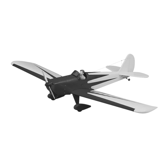
Preflight................18 building or flying skills. With its thick airfoil and light wing Charge the Batteries ..........18 loading, the SpaceWalker is great for a day of relaxed Balance the Propeller..........18 flying. What more can we say? Impress your flying buddies Find a Safe Place to Fly..........19 and maximize your fun for minimal cost and time! Ground Check the Model ...........19... -
Page 3: Decisions You Must Make
Sandpaper (coarse, medium, fine grit) ™ Easy-Touch Bar Sander (GPMR6170, or similar) There are several engines that will work well in your Paper Towels SpaceWalker ARF. We recommend a hot 2-stroke such Electric Drill as an O.S. ® .61FX or SuperTigre ™... -
Page 4: General Inspection
Tele. (913) 823-5569 If you intend to fly the SpaceWalker ARF at IMAA events, it may be necessary to replace the 2-56 pushrods, clevises and control horns with 4-40 pushrods, clevises and control horns designed for 1/4 scale airplanes. Although the plane flies great with the hardware supplied, many events require the use of 4-40 style hardware. -
Page 5: Parts List
Landing Gear Straps 2-56 x 12" Threaded Pushrod 5mm x 50.8mm Wing Bolt Replacement Parts Parts Included in the Hardware Bag If needed, replacement parts for SpaceWalker ARF are available through Inner Throttle Pushrod your hobby supplier. 2-1/2" Main Wheels 2-1/2" Spinner Canopy ..................GPMA2163... -
Page 6: Wing Assembly
WING ASSEMBLY Join the Two Wing Halves 3. Use a sharp hobby knife to cut the covering from the wing dowel holes in the leading edge and the wing bolt holes at the trailing edge of each wing half. The wing dowel holes are approximately 2"... -
Page 7: Mount The Wing To The Fuselage
wing halves together, removing any excess epoxy with a paper towel dampened with isopropyl alcohol. Use masking tape to hold the wing halves together while the epoxy cures. 4. Use a sharp hobby knife to trim the covering from the wing, 1/8"... -
Page 8: Install The Rudder, Elevators And Ailerons
Stretch the string to one corner of the stabilizer. Repeat the carefully to obtain the best results. These instructions procedure on the other side of the stabilizer. Adjust the may be used to effectively install any of the various angle of the stabilizer until the distance from the pin to the brands of CA hinges. - Page 9 wire against the fuselage. Mark the four mounting holes in the tailgear mount. 6. At each mark drill a 1/16" [1.6mm] pilot hole. Attach the tailgear to the bottom of the fuselage with four #2 x 3/8" sheet metal screws. 2.
-
Page 10: Install The Main Landing Gear
paper towel dampened in isopropyl alcohol to wipe off any excess epoxy before it cures. 4. Position the wheel pant bracket on the wheel INSTALL THE MAIN LANDING GEAR pant, centered over the axle guide hole. Mark the two bracket mounting holes on the wheel pant. A T-pin works great for this. -
Page 11: Engine Installation
#8 flat washer to seat the blind nuts in the back of the firewall. 4. Cut the “spreader bar” from the supplied Great Planes adjustable engine mount. Use a hobby knife to remove any flashing left over from the molding process so that the 9. -
Page 12: Radio Installation
2. Install the receiver switch on the left side of the pushrod tube and pushrod connector. Install a 4-40 x 1/8" fuselage. We prefer a Great Planes Switch & Charge Jack socket head cap screw in the pushrod connector. Mounting Set (GPMM1000). This allows the receiver battery... - Page 13 5. If you installed a 2-stroke engine on your plane, install the muffler and bend the throttle pushrod as needed to avoid interference between the muffler. 6. Switch your radio system on. Check that the throttle opens and closes completely using the throttle stick and trim on the transmitter.
-
Page 14: Install The Aileron Servos
a nylon Faslink. Cut the excess pushrod so it slightly 22. Attach a control horn to both clevises. Align the protrudes out of the Faslink. adjustment holes in the control horns with the hinge line of the elevator. Mark the control horn’s mounting holes. Note: If necessary, enlarge the hole in the servo arm with a 5/64"... -
Page 15: Install The Cowl
Note: If necessary, enlarge the hole in the servo arm with a 5/64" [2mm] drill bit (or a #48 drill for precision). 9. Return to step 1 of “Install The Aileron Servos” and install the second aileron servo. Note: Install the servo arms so that they both point outward, toward the wing tips. -
Page 16: Adding Details To Your Spacewalker Arf
8. When satisfied with the fit of the cowl, install the spinner backplate, propeller and spinner cone on the engine. 4. For convenience, we installed on the left side of the firewall, a Great Planes Easy Fueler ™ Fuel Filling Valve (GPMQ4160) mounted on a piece of 1/8"... -
Page 17: Set The Control Throws
This chart indicates the settings at which the SpaceWalker ARF flies best. Please set up your model to the specifications listed above. If, after you 5. We used a Williams Brothers 1/4 scale old time pilot become comfortable with your SpaceWalker ARF, you #62500 raised up with a 1/2"... -
Page 18: Balance Your Model
Note: This is the balance point at which your model should several times. balance for your first flights. After initial trim flights and when you become more acquainted with your SpaceWalker 2. The wing that consistently drops indicates the heavy ARF, you may wish to experiment by shifting the balance side. -
Page 19: Find A Safe Place To Fly
We use a Top Flite ® Precision Magnetic Prop Balancer ™ (TOPQ5700) in the workshop and keep a Great Planes Note: Failure to follow these safety precautions may Fingertip Balancer (GPMQ5000) in our flight box. result in severe injury to yourself and others. -
Page 20: Ama Safety Code (Excerpt)
2. I will not fly my model aircraft in the presence of We recommend that you take it easy with your SpaceWalker spectators until I become a qualified flier, unless assisted ARF for the first several flights, gradually “getting... -
Page 21: Landing
17. Sometime well before it’s time to land, you should climb your SpaceWalker ARF to a safe altitude, reduce the throttle to an idle and check out the model’s low speed characteristics. Do this a few times so you know what to expect upon landing and how the SpaceWalker ARF handles stalls. - Page 22 O.S. .91 Surpass Engine (OSMG0895) Accu–Cycle takes over. Tx and Rx packs can be cycled Give a sharper kick to your Spacewalker’s aerobatic alone or simultaneously. Separate LED screens provide maneuvers with the 1.6 horsepower (at 11,000 rpm) O.S.
- Page 23 TorqMaster starter. GPMR8500 Bench Topper ™ The Great Planes Bench Topper holds the inexpensive answer to building supply storage and organization hassles. It assembles quickly into a 15.5" long x 7.5" high x 5.25" deep caddy that fits comfortably on any bench – or can be mounted conveniently on a wall.
-
Page 24: Building Notes
BUILDING NOTES Kit Purchased Date Date Construction Finished Where Purchased Finished Weight Date Construction Started Date Of First Flight FLIGHT LOG...
Need help?
Do you have a question about the spacewalker and is the answer not in the manual?
Questions and answers