GREAT PLANES Piper j-3 cub Instruction Manual
Hide thumbs
Also See for Piper j-3 cub:
- Instruction manual (6 pages) ,
- Instruction manual (16 pages) ,
- Instruction manual (24 pages)
Table of Contents
Advertisement
Great Planes
®
Model Manufacturing Co. guarantees this kit to
be free from defects in both material and workmanship at the date
of purchase. This warranty does not cover any component parts
damaged by use or modification. In no case shall Great Planes'
liability exceed the original cost of the purchased kit. Further,
Great Planes reserves the right to change or modify this warranty
without notice.
In that Great Planes has no control over the final assembly or
material used for final assembly, no liability shall be assumed nor
accepted for any damage resulting from the use by the user of the
final user-assembled product. By the act of using the user-
assembled product, the user accepts all resulting liability.
If the buyer is not prepared to accept the liability associated
with the use of this product, the buyer is advised to return
READ THROUGH THIS MANUAL BEFORE STARTING
CONSTRUCTION. IT CONTAINS IMPORTANT INSTRUCTIONS
AND WARNINGS CONCERNING THE ASSEMBLY AND
USE OF THIS MODEL.
CUB4P03 for GPMA0160 V3.0 Printed in USA
INSTRUCTION MANUAL
WARRANTY
this kit immediately in new and unused condition to the place
of purchase.
To make a warranty claim send the defective part or item to Hobby
Services at the address below:
Include a letter stating your name, return shipping address, as
much contact information as possible (daytime telephone number,
fax number, e-mail address), a detailed description of the problem
and a photocopy of the purchase receipt. Upon receipt of the
package the problem will be evaluated as quickly as possible.
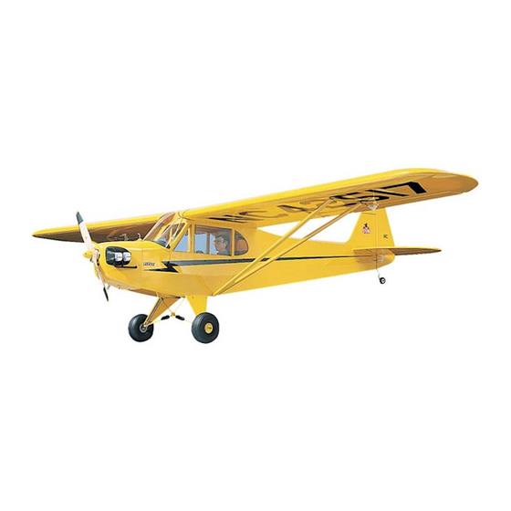
Wingspan (Standard): 76.5 in [1,945mm]
Wingspan (Clipped): 61.5 in [1,560mm]
Wing Area (Standard): 820 sq in [58.9dm
Wing Area (Clipped): 653 sq in [42.1dm
Weight: 6.5-7.5 lbs [2950-300g]
Wing Loading: 18-21 oz/sq ft [55-64g/dm
Length: 49 in [1,245mm]
Radio: 4-channel transmitter with 4 standard servos
Engine: .40-.61 cu. in. [6.5-10cc] two-stroke
.48-.80 cu. in. [8-13cc] four-stroke
Hobby Services
3002 N. Apollo Dr. Suite 1
Champaign, IL 61822
USA
Champaign, IL
(217) 398-8970, Ext. 5
airsupport@greatplanes.com
Entire Contents © Copyright 2003
2
]
2
]
2
]
Advertisement
Table of Contents

Subscribe to Our Youtube Channel
Related Manuals for GREAT PLANES Piper j-3 cub


Summary of Contents for GREAT PLANES Piper j-3 cub
-
Page 1: Instruction Manual
Hobby Services 3002 N. Apollo Dr. Suite 1 In that Great Planes has no control over the final assembly or Champaign, IL 61822 material used for final assembly, no liability shall be assumed nor accepted for any damage resulting from the use by the user of the final user-assembled product. -
Page 2: Table Of Contents
Balance the Airplane Laterally........38 For the latest technical updates or manual corrections to the Final Sanding.............38 Piper J-3 Cub .40, visit the web site listed below and select Covering..............38 the Great Planes Piper J-3 Cub .40. If there is new technical Apply Decals and Trim ..........39... -
Page 3: Precautions
(Piper J-3 Cub .40) and the part numbers as listed 1.Your Piper J-3 Cub .40 should not be considered a toy, but in the Parts List. rather a sophisticated, working model that functions very much like a full-size airplane. -
Page 4: Wing Configuration
In addition to common household tools (screwdrivers, drill, Wing Configuration etc.), this is the “short list” of the most important items required to build the Piper J-3 Cub .40. We recommend This kit includes everything you need to build either the Great Planes Pro CA and Epoxy glue. -
Page 5: Important Building Notes
™ instructions will make a recommendation. A flat, durable, easy to handle sanding tool is a necessity for building a well finished model. Great Planes makes a • Whenever just epoxy is specified you may use either complete range of Easy-Touch Bar Sanders and replaceable 30-minute (or 45-minute) epoxy or 6-minute epoxy. -
Page 6: Types Of Wood
TYPES OF WOOD GET READY TO BUILD 1. Unroll the plan sheet. Re-roll it inside out to make it lie flat. 2. Remove all parts from the box. As you do, figure out the name of each part by comparing it with the plans and the parts list included with this kit. - Page 7 DIE-CUT DRAWINGS 1/64" = .4 mm 3" = 76.2 mm METRIC CONVERSIONS 1/32" = .8 mm 6" = 152.4 mm 3/8" = 9.5 mm 1/16" = 1.6 mm 12" = 304.8 mm 1/2" = 12.7 mm 3/32" = 2.4 mm 18"...
-
Page 8: Tail Feathers
TAIL FEATHERS Build the Rudder 3. Cut the four Ribs from the 3/16” x 1/4” x 24” balsa stick (CUB4SO4). Fit the ribs into the rudder frame and securely glue them in place with thin CA. 4. Remove the Rudder from the building board and 1. -
Page 9: Build The Fin
make sure all the joints are good and tight. Securely glue all the joints with thin CA. Note: The bottom end of the trailing edge stops at the top edge of the horizontal stabilizer. 8. Check the plans and mark the location of the tailgear on the rudder. -
Page 10: Build The Elevators
2. Position the S1 and the two S4’s over their locations on the plans. Check the fits of the joints and sand them if necessary. Pin them in place. 2. Cut the Elevator LE from the 1/4" x 3/4" x 24" balsa strip (CUB4S03) and pin it in place. -
Page 11: Cut The Hinge Slots
11. Test fit the joiner wire into both elevators. Position the elevators against a straight edge to check for straightness of the LE with the joiner wire installed. Adjust the holes if needed to achieve a straight LE. 2. Cut the hinge slots on the centerlines which you previously drew, using a hobby knife following the 12. - Page 12 first two #3 ribs. Keep the plans aligned and tape the Align the end of the spar with the outboard edge of rib #7. inner and outer halves together. The plans are now The spars are cut slightly too long, and the excess will be ready to use for the clipped wing version.
- Page 13 9. Carefully inspect the notches in the die-cut 1/8" balsa Outboard TE (CUB4F03). The 1/8" wide notches are to be aligned with the #6 rib locations. Insert the tab on the die-cut outboard TE into the slot at the aft end of the #4 rib, with the notches facing up.
- Page 14 the #7 rib. Align the top notch in the wing tip brace with the 23. Install rib #2 by sliding it in between the spars and #8 rib on the plans and glue the brace in place. Make sure twisting it into place. Center it on the LE and glue it with thin the “legs”...
-
Page 15: Joining The Wing Panels
30. Remove the wing panel from the work surface and install the 1/8" x 1/4" x 33-1/2" Bottom Forward Spar 27. Place the die-cut 1/8" balsa triangular Gusset (CUB4W12) following the same procedure used in step 25. (CUB4W01) in the corner formed by the #4 rib and the tapered TE. - Page 16 4. IMPORTANT: Use a good quality non-brittle epoxy for this task, such as Great Planes Pro 30-minute Epoxy. Place waxed paper on the work surface and mix up a batch of epoxy. Apply it to the top and bottom of the dihedral brace, the spar joiners, the spars, spar ends and the ends of both TE’s.
-
Page 17: Install The Aileron Linkage
10. Glue the die-cut 1/16" ply TE Joiner (CUB4W05) in place between the #1B ribs as shown in the photo. (Wing is upside down in photo.) 13. Hold your aileron servo in position against the servo rails and mark where to drill the mounting holes. Drill 1/16" holes at each mark and mount your servo using the screws provided with the servo. -
Page 18: Install Le And Te Sheeting
20. Cut the 36" long Outer Pushrod Tube (PLTB011) into 17. Cut eight pieces of the Inner Pushrod Tube (PLTB004) two 18" long pieces. Scuff up the outer surface of each approximately 1/4" long to make the pushrod wire spacers. pushrod tube with 150 grit sandpaper so the glue will Slide four spacers on each of the 24"... - Page 19 5. Wet the LE sheeting with a wet paper towel from rib #7 to the end of the sheet. Form the sheeting down against the 2. Prepare the 1/16" x 1-1/2" x 36" balsa Top Leading Edge wing tip and glue along the LE and the edge of the wing tip. Sheeting (CUB4W25) by sanding the front edge to a slight Hold the sheeting against the wing tip until the glue sets.
-
Page 20: Install Center Sheeting
the edges smooth with a piece of fine (220 grit) sandpaper. Use Install Center Sheeting extreme caution to avoid cutting into the spars! 1. Use a sanding block to sand off any excess epoxy on the top and bottom of the spars in the center of the wing. Also lightly sand both the tops and bottoms of each rib to remove any glue bumps or other irregularities. -
Page 21: Build The Ailerons
8. Sand the front and side TOP edges of the die-cut 1/16" 5. Use a razor plane and a T-bar or other good flat plywood Wing Bolt Plate (CUB4W05) to a feathered edge. sanding block to shape the ribs to the cross section shown Leave the TE square. -
Page 22: Install Ailerons
plans. This goes on the bottom of each aileron. Sand it to match the shape of the ribs. Install Ailerons NOTE: Do not glue the aileron hinges until after your model has been covered. 1. Lay the ailerons on the plan and mark the hinge locations on the ailerons. -
Page 23: Fuselage Assembly
against the aileron pushrod outer tube and glue them to 3. Remove the fuse side from the plans and inspect several of the ribs as shown in the photo. Securely glue the the glue joints for gaps, adding thick CA glue to any open outer pushrod tube wherever possible. - Page 24 9. Test fit the two die-cut 1/8" balsa Aft Fuse Tops (CUB4F05) together. Sand them if necessary to achieve a good fit and glue them together as shown in the photo. 13. Glue one of the 1/8" x 2-3/8" x 2-3/8" ply Firewall Doublers (CUB4F18) to former F1B so that it is centered over the engine mount holes as shown in the photo.
-
Page 25: Assemble Fuselage
Assemble Fuselage 4. Position the right fuse side in place so all four formers key into their slots. Tack glue the fuselage side to the formers. Do not apply glue to the joints near the TOP of former F3, because you will later (step 6) have to spread the fuse sides to install the wing mounting block. - Page 26 8. Insert the top tab of the die-cut 1/8" ply Cabin Brace (CUB4F12) into the notch at the bottom of former F2B. Insert the die-cut 1/8" ply Top Tank Floor (TTF) (CUB4F09) with the embossed “TTF” facing upward, rear tabs into the top notches of former F2.
- Page 27 14. Cut two 4-3/4" long sheets from the 3/32" x 3" x 12" balsa Nose Sheeting (CUB4F16). Glue one piece of sheeting to the right fuselage side and stringer so the corner of it is against the cabin side. Do not bend it around the firewall yet. Firmly apply 17.
-
Page 28: Install Engine Mount And Fuel Tank
2. Place the left side of the engine mount on the mount spacer and center it on the diagonal lines you just drew. Mark 20. Insert the die-cut 1/8" ply Top Deck Former #4 the mounting holes on the diagonal lines and then drill a 3/16" (CUB4F11) into its slot at the tail end of the balsa aft fuse hole at each mark. -
Page 29: Final Fuselage Assembly
6. While the engine is still mounted, determine where the Final Fuselage Assembly fuel lines and the throttle pushrod should pass through the firewall and mark these locations. NOTE: With most tank and engine combinations, the fuel lines can pass through the center of the mount. -
Page 30: Mount Stabilizer And Fin
4. Sand the bottom edges of the fuselage smooth with your sanding block. Use the 3/32" x 2-3/4" x 24" balsa Bottom Sheeting (CUB4F15) to sheet the bottom of the fuselage from the grooved landing gear block forward and from the 2. - Page 31 tubes flush with the covering supports. Sand a slight taper into the covering supports so they will not bulge the covering when it is applied. 6. Refer to the fuselage plans to determine the placement of the 3/16" x 3/16" x 36" balsa Fuselage Side Stringer (CUB4F15).
-
Page 32: Install Main Landing Gear
Install Main Landing Gear 3. Position Nylon LG Straps (NYLON36) over the landing gear wire approximately 1" from the bends in the landing gear wires. Mark the locations of the mounting screws on the grooved block. Drill a 1/16" hole at each of these marks. 1. -
Page 33: Mount The Wing To The Fuse
shown in the photo. Cut the protruding part of each #2 x 3/8" screw off on the outside of the fairings and sand (or file) the screws flush with the fairing. Use a small rubber band near the wheel end of the fairing to allow the strut to move against the fairing. -
Page 34: Install Servos, Horns And Pushrods
Install Servos, Horns and Pushrods 1. Hold the Large Nylon Control Horns on the elevator and rudder in the positions shown on the fuselage plan and mark the mounting hole locations. REMEMBER: The elevator horn is located on the bottom of the elevator! Drill 5. -
Page 35: Control Throws
trace around the strap. NOTE: Make two Right and two Left These are the recommended control surface throws struts and keep in mind that these straps are on the top of (NOTE: Throws are measured at the widest part of the the outboard end of the struts. -
Page 36: Install Receiver, Switch And Battery
of the wings are level. Drill a 1/16" hole in the middle of each wing strut mounting block and screw a strut to each block using a #2 x 1/2" Button Head Screw (SCRW088). Mark where the struts cross the fuse side and cut them off at the marks. -
Page 37: Install Cowl
4. Mount the on-off switch wherever convenient. We used and the prop. It is sometimes easier to take the muffler off the Great Planes Switch and Charge Jack Mounting Set during the early stages of fitting and get the cowl to fit the (GPMM1000) which makes it very easy to charge the engine itself first. -
Page 38: Additional Fuelproofing
HINT: Access to the fuel lines can be a problem in a cowled edge to overlap (1/8"+ overlap) the strips you engine; therefore, we suggest that you install a Great Planes previously applied. DO NOT, under any circumstances, Easy Fueler (GPMQ4160) valve. This makes it much easier attempt to cut the covering material after it has been to fill and empty your tank. -
Page 39: Apply Decals And Trim
wire elevator joiner. Reinstall the rudder and check the 3. Rudder right side notch. The notch should be large enough to allow the rudder 4. Bottom of elevators to freely move throughout its entire range of motion. 5. Top of elevators 6. -
Page 40: Painting The Pilot (Optional)
Painting the Pilot (Optional) 5. Position the seat backs over the 1/16" holes you drilled 1. We used a 1/5 scale Williams Brothers #185 Sportsman earlier in the cockpit floor. Screw the seat backs to the cockpit Pilot. Assemble your pilot and then glue it to a 1/2" thick balsa floor using #2 or #4 sheet metal screws (not included). -
Page 41: Build The Dummy Engines
4. Make the “Shocks” by drilling a 3/32" hole through the middle of a 5/16" x 5/16" x 1-1/4" long piece of balsa. Use 2. Cut the Engine Shroud out along the trim line and your hobby knife to carve a few irregular slices out of the sand its edges smooth. -
Page 42: Other Scale Details
Other Scale Details 5. A scale prop can be made using a regular Top Flite 1. You can make a simple step out of scrap pushrod wire. 10 x 6 Power Point Prop. Round off the ends using sandpaper Drill 5/64" holes just behind the left LG fairing and glue it in and use a little bit of dark stain to give the prop a darker color place as shown in the photo. -
Page 43: Install The Side Windows
Balance Your Model NOTE: This section is VERY important and must not be omitted! A model that is not properly balanced will be unstable and possibly unflyable. 1. Accurately mark the balance point on the bottom of the wing on both sides of the fuselage. The balance point is shown on the plan (CG), and is located approximately 4"... -
Page 44: Preflight
2. Adjust your pushrod hookups as necessary to provide Find a Safe Place to Fly the proper control surface movements as listed on Page 38. *NOTE: These control surface “throws” are approximate and The best place to fly your R/C model is an AMA (Academy of provide a good starting point for the first flights with your J-3 Model Aeronautics) chartered club field. -
Page 45: Ama Safety Code
near the engine or fuel; remember that the engine exhaust 3. Where established, I will abide by the safety rules for the gives off a great deal of deadly carbon monoxide. Therefore flying site I use, and I will not willfully and deliberately fly my do not run the engine in a closed room or garage. - Page 46 Flying CAUTION (THIS APPLIES TO ALL R/C AIRPLANES) If, while flying, you notice any unusual sounds, such as a We recommend that you take it easy with your J-3 CUB for the low-pitched “buzz”, this may be an indication of control first several flights and gradually “get acquainted”...
- Page 47 BUILDING NOTES Kit Purchased Date: _______________________ Date Construction Finished: _________________ Where Purchased:_________________________ Finished Weight: __________________________ Date Construction Started: __________________ Date of First Flight: ________________________ FLIGHT LOG...
- Page 48 Two-View Diagram Use this drawing for planning your trim scheme.
Need help?
Do you have a question about the Piper j-3 cub and is the answer not in the manual?
Questions and answers