Table of Contents
Advertisement
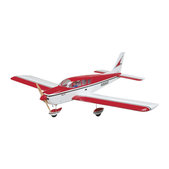
Wingspan: 60 in [1520mm]
2
2
Wing Area: 606 in
[39dm
]
Weight: 6.75 – 7.25 lb [3060 – 3290g]
2
Wing Loading: 26 – 28 oz/ft
[79 – 85g/dm
Length: 46 in [1170mm]
Radio:
4-channel minimum with four to seven
standard servos and standard size receiver
Engine: .40 – .46 cu in [7 – 7.5cc] two-stroke,
.56 cu in [9.2cc] four-stroke,
42-50-800kV brushless out-runner motor
Great Planes
®
Model Manufacturing Co. guarantees this kit to be free from defects in both material and workmanship at the date of purchase.
This warranty does not cover any component parts damaged by use or modifi cation. In no case shall Great Planes' liability exceed the
original cost of the purchased kit. Further, Great Planes reserves the right to change or modify this warranty without notice.
In that Great Planes has no control over the fi nal assembly or material used for fi nal assembly, no liability shall be assumed nor accepted
for any damage resulting from the use by the user of the fi nal user-assembled product. By the act of using the user-assembled product,
the user accepts all resulting liability.
If the buyer is not prepared to accept the liability associated with the use of this product, the buyer is advised to return this kit
immediately in new and unused condition to the place of purchase.
To make a warranty claim send the defective part or item to Hobby Services at the address below:
Include a letter stating your name, return shipping address, as much contact information as possible (daytime telephone number, fax
number, e-mail address), a detailed description of the problem and a photocopy of the purchase receipt. Upon receipt of the package
the problem will be evaluated as quickly as possible.
READ THROUGH THIS MANUAL BEFORE
STARTING CONSTRUCTION. IT CONTAINS
IMPORTANT INSTRUCTIONS AND WARNINGS
CONCERNING THE ASSEMBLY AND USE OF
THIS MODEL.
Entire Contents © Copyright 2008
INSTRUCTION MANUAL
2
]
WARRANTY
Hobby Services
3002 N. Apollo Dr., Suite 1
Champaign, IL 61822 USA
Champaign, Illinois
(217) 398-8970, Ext 5
airsupport@greatplanes.com
GPMZ1033 for GPMA1033 V1.0
Advertisement
Table of Contents

Subscribe to Our Youtube Channel
Related Manuals for GREAT PLANES Cherokee .40 ARF


Summary of Contents for GREAT PLANES Cherokee .40 ARF
- Page 1 Further, Great Planes reserves the right to change or modify this warranty without notice. In that Great Planes has no control over the fi nal assembly or material used for fi nal assembly, no liability shall be assumed nor accepted for any damage resulting from the use by the user of the fi...
-
Page 2: Table Of Contents
In those instances the written Cherokee .40 ARF built in as little as 4 to 6 hours. Just like its full-scale counterpart, the Cherokee .40 ARF is extremely... -
Page 3: Decisions You Must Make
6. You must check the operation of the model before every fl ight to insure that all equipment is operating and that the The Cherokee .40 ARF requires a minimum 4-channel radio model has remained structurally sound. Be sure to check system with four to seven 44 oz.-in. -
Page 4: Propeller
Required Hardware & Accessories Propeller This is the list of hardware and accessories required to fi nish the Cherokee .40 ARF. Order numbers are provided in parentheses: If you are installing a glow engine, choose a prop based on the engine manufacturer’s recommendation. If you are ❏... -
Page 5: Building Stand
Great Planes clevis installation tool (GPMR8030) BUILDING STAND ORDERING REPLACEMENT PARTS Replacement parts for the Great Planes Cherokee .40 ARF are available using the order numbers in the Replacement Parts List that follows. The fastest, most economical service can be provided by your hobby dealer or mail-order company. -
Page 6: Common Abbreviations
If additional assistance is required for any reason contact Product COMMON ABBREVIATIONS Support by e-mail at productsupport@greatplanes.com, or by telephone at (217) 398-8970. Stab = Horizontal Stabilizer Replacement Parts List Fin = Vertical Fin LE = Leading Edge Description How to Purchase TE = Trailing Edge Missing pieces Contact Product Support... -
Page 7: Kit Inspection
If any parts are missing or are not of acceptable quality, or if you need assistance with assembly, contact Product Support. When reporting defective or missing parts, use the part names exactly as they are written in the Kit Contents list. Great Planes Product Support: 3002 N. Apollo Drive, Suite 1 Champaign, IL 61822 Telephone: (217) 398-8970, ext. -
Page 8: Preparations
over the rectangles with the grain direction perpendicular to PREPARATIONS the covers. Allow the epoxy to cure undisturbed. ❏ 1. If you have not done so already, remove the major parts of the kit from the box and inspect for damage. If any parts are damaged or missing, contact Product Support at the address or telephone number listed in the “Kit Inspection”... - Page 9 ❏ ❏ 5. Use the string taped inside the aileron servo bay to pull the servo lead through the wing ribs. ❏ ❏ 8. Position the control horn over the plywood plate in the aileron (if you cannot see it, hold the aileron at a shallow angle in good lighting or use a small pin to puncture the covering), using the position of the servo arm as a guide.
- Page 10 ❏ ❏ 12. Install a control horn onto the fl ap using two #2 x 3/8" [9.5mm] screws. Make note that these screws are shorter than the ones used for the aileron control horns. As you did with the aileron, install a 4" [102mm] pushrod onto the fl ap. Before connecting the pushrod to the fl...
-
Page 11: Fixed Flaps
BUILD THE FUSELAGE Fixed Flaps If you are not installing operational fl aps, follow these steps Install the Tail Surfaces to lock the fl aps into the neutral position. If in the future you choose to add operational fl aps, simply cut the ABS strips along the inside edge of each fl... -
Page 12: Install The Tail Servos & Pushrods
Install the Tail Servos & Pushrods ❏ 1. Cut two arms from a four-armed servo arm and enlarge the outer hole of one remaining arm with a 5/64" [2mm] drill bit and the second inner hole of the other remaining arm with the same bit. -
Page 13: Glow Engine Installation
Mount the elevator servo next to the rudder servo with a gap of approximately 1/4" [6mm] between the tips of The Cherokee .40 ARF is designed to be fl own with a .40 to the servo arms. Leave enough room for the throttle servo. - Page 14 ends of each side by approximately 2" [51mm]. Insert the straps into the slots in the plywood fuel tank tray as shown. ❏ 4. Fit the fuel tank tray into the fuselage by inserting the tab at the forward end of the tray into the slot in the fi rewall. Press the tray down onto the receiving tabs in the fuselage former and cross brace.
- Page 15 the engine head will be on the right side. Leave the screws slightly loose. Test fi t your engine between the mount halves. Slide the mount halves against the sides of the engine and fi nish tightening the mount screws. ❏...
-
Page 16: Brushless Motor Installation
into the third outer hole in the remaining servo arm, with a Brushless Motor Installation 4-40 set screw loosely threaded into the connector. Center the throttle servo with your radio system and install the servo arm onto the servo as shown. Use the hardware included If you have installed a glow engine, skip this section as it only with the servo and install it next to the elevator servo. - Page 17 CA. ❏ 3. If using the Great Planes ESC, install it to the mounting tray using three #4 x 1/2" [13mm] self-tapping screws. Be sure to harden the holes with thin CA. If installing another...
-
Page 18: Assemble & Install The Landing Gear
battery pack. Also use some self-adhesive hook and loop screws against the fl at spots on the axles. Be sure that the material to join the 11.1V and 7.4V packs together. The straps wheels rotate freely on the axles. Oil the axles if necessary. you made in step 4 are used to securely hold the battery packs onto the tray. - Page 19 ❏ 6. Fit a 5/32" [4mm] wheel collar into the nylon steering arm, aligning the threaded hole in the collar with the hole in the arm. Loosely thread a 6-32 x 1/4" [6mm] SHCS (with threadlocking compound) through the hole in the arm and into the collar.
-
Page 20: Finish The Model
fi rewall. A piece of white MonoKote is included with the Cherokee .40 ARF for covering up the area that was carved ❏ 2. Connect the servos to the receiver, being sure that the away. -
Page 21: Install The Cowl, Spinner & Propeller
❏ 3. Fit the cowl to the fuselage and align it with the colors on the fuselage. When satisfi ed with the fi t, tape the cowl into position. Measure 3/8" [9.5mm] forward from the aft end of the cowl at each mark you made on the masking tape. Mark the cowl for each of the four cowl mounting screws. -
Page 22: Install The Wing & Canopy Hatch
Install the Wing & Canopy Hatch ❏ 4. This completes the assembly of the Cherokee .40 ARF! Apply the Decals 1. Use scissors or a sharp hobby knife to cut the decals from the sheet. 2. Be certain the model is clean and free from oily fi ngerprints and dust. -
Page 23: Battery Precautions/Connecting Batteries
Adjust if necessary. Batteries of different voltages, but not different capacities may also be connected in Series: Set the Control Throws Use a Great Planes AccuThrow ™ (or a ruler) to accurately measure and set the control throw of each control surface as indicated in the chart that follows. -
Page 24: Balance The Model (C.g.)
fl ights. If, after you have become accustomed to the way is “nose heavy” and the battery pack and/or receiver must be the Cherokee .40 ARF fl ies, you would like to change the shifted aft or weight must be added to the tail to balance. If throws to suit your taste, that is fi... -
Page 25: Balance The Model Laterally
We use a Top Flite Precision Magnetic Prop Balancer (TOPQ5700) in the workshop and keep a Great Planes Fingertip Prop Balancer (GPMQ5000) in our fl ight box. -
Page 26: Engine Safety Precautions
ENGINE SAFETY PRECAUTIONS LITHIUM BATTERY HANDLING & USAGE WARNING!! Read the entire instruction sheet included with Failure to follow these safety precautions may result your battery. Failure to follow all instructions could cause in severe injury to yourself and others. permanent damage to the battery and its surroundings, and cause bodily harm! Keep all engine fuel in a safe place, away from high heat,... -
Page 27: Check List
FLYING During the last few moments of preparation your mind may The Cherokee .40 ARF is a great-fl ying model that fl ies be elsewhere anticipating the excitement of the fi rst fl ight. smoothly and predictably. The Cherokee .40 ARF does... -
Page 28: Flight
After you have the feel of the Cherokee .40 ARF, takeoffs may be made with the fl aps set at 50%. Full fl aps make the Cherokee .40 ARF very steady in the landing pattern, but just carry a little extra power to make Flight up for the extra drag.
Need help?
Do you have a question about the Cherokee .40 ARF and is the answer not in the manual?
Questions and answers