Table of Contents
Advertisement
Quick Links
WARNING: If the information in these instructions is not followed exactly, a fire or
explosion may result causing property damage, personal injury or loss of life.
-
Do not store or use gasoline or other flammable vapors and liquids in the vicinity of this or
any other appliance.
WHAT TO DO IF YOU SMELL GAS
• Do not try to light any appliance.
• Do not touch any electrical switch; do not use any phone in your building.
• Immediately call gas supplier from a neighbor's phone. Follow the gas supplier's instructions.
• If you cannot reach your gas supplier, call the fire department.
-
Installation and service must be performed by a qualified installer, service agency or the gas
supplier.
This appliance may be installed in an
aftermarket permanently located,
manufactured home (USA only) or mobile
home, where not prohibited by local
codes.
This appliance is only for use with the
type(s) of gas indicated on the rating plate.
A conversion kit is supplied with the
appliance.
INSTALLER:
Leave this manual with the appliance.
CONSUMER:
Retain this manual for future reference.
Copyright 2012, T.I.
$10.00
100-01271_000
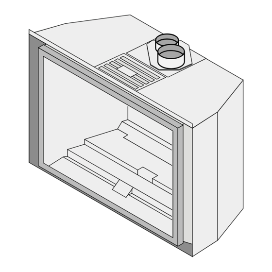
616 GSR Insert
Owner's Manual
Tested and Listed by
ANSI Z21.88 CSA 2.33
Direct Vent Fireplace Insert
Masonry or Factory Built (Metal) Wood-
Burning Fireplace
Residential or Mobile Home
4051112
4800 Harbour Pointe Blvd. SW
Travis Industries, Inc.
www.travisproducts.com
Mukilteo, WA 98275
Advertisement
Table of Contents

Related Manuals for Travis Industries 616 GSR Green Smart


Summary of Contents for Travis Industries 616 GSR Green Smart
- Page 1 This appliance is only for use with the type(s) of gas indicated on the rating plate. A conversion kit is supplied with the appliance. INSTALLER: Leave this manual with the appliance. Travis Industries, Inc. CONSUMER: Retain this manual for future reference. www.travisproducts.com Copyright 2012, T.I. $10.00...
-
Page 2: Introduction
This serial number will be needed in case you require Or, mail your warranty card to: service of any type. Travis Industries House of Fire 4800 Harbour Pointe Blvd. SW Model: 616 GSR Mukilteo, WA 98275 Serial Number: Save Your Bill of Sale. -
Page 3: Table Of Contents
Steps for Finalizing the Installation ..... 25 IF WARRANTY SERVICE IS NEEDED: ..47 Air Shutter Adjustment ........26 LP Conversion Instructions ......48 Burner Removal ..........27 Before You Begin ........... 30 4051112 © Travis Industries 100-01271_000... - Page 4 Immediately call a qualified vicinity of this heater. service technician to inspect the appliance and to replace any part of the control system that has been under water. © Travis Industries 4051112 100-01271_000...
- Page 5 (except the media). a later time. Always follow the • If the media becomes damaged, instructions in this manual. replace with Travis Industries media set. Young children should be carefully • Plug the heater into a 120V grounded electrical outlet. Do supervised when they are in the not remove the grounding plug.
-
Page 6: Features
This heater is shipped in natural gas (NG) configuration but may be converted to propane (LP) using the LP Conversion Kit (included) and the LP stepper motor (SKU 94400999, sold separately). The sticker on top of the gas control valve will verify the correct fuel. © Travis Industries 4051112 100-01271_000... -
Page 7: Installation Warnings
8. Install the media (logs, stones - see instructions included with the media). 9. Install the surround panel (see instructions included with surround panel). 10. Replace the glass. 11. Install the face (see instructions included with the face). 12. Follow the instructions under “Finalizing the Installation.” 4051112 © Travis Industries 100-01271_000... -
Page 8: Fireplace Requirements
You may wish to place it in a location where it will be covered by the surround panels. Fireplace Clearances to Gas Insert Side of Insert to Inside of Fireplace ½” (13mm) Back of Insert to Inside of Fireplace ½” (13mm) Top of Insert to Inside of Fireplace 5/8” (18mm) © Travis Industries 4051112 100-01271_000... -
Page 9: Factory-Built (Metal) Wood-Burning Fireplace Requirements
½” of non-combustible material must extend 12” in front of the insert for the full width of the unit (34”). RAISED INSERTS: If the insert is raised a minimum of 16” above the flooring (or other combustible material), a non-combustible hearth is not required in front of the insert. 4051112 © Travis Industries 100-01271_000... -
Page 10: Leveling Bolts
This heater includes front and rear leveling bolts to accommodate fireplaces with a step-down firebox. NOTE: To access the rear leveling bolts, remove the burner (see page 48). The leveling bolt holes are shown below. 1. Remove the cover and gasket to access the rear leveling bolt. © Travis Industries 4051112 100-01271_000... -
Page 11: Electrical Requirements
If it does, it is considered a mantel and must meet the mantel requirements listed in this manual. Maximum Mantel Depth 37"+(940mm+) 36"(915mm) 35"(889mm) Mantel Height 34"(864mm) Above Base of Insert (n) 33"(839mm) 32"(813mm) 31"(788mm) 4051112 © Travis Industries 100-01271_000... -
Page 12: Gas Line Requirements
5/16” i.d. rubber or plastic tubing over the tapered test port. Connect the tubing to the test gauge. WARNING: The brass screw must be tightened after testing to prevent gas leakage. Output pressure Input pressure © Travis Industries 4051112 100-01271_000... -
Page 13: Gas Line Installation
Bend the flex tube up as shown below. Attach the included gas shutoff valve to the end of the flex tube and gas inlet as shown below. Position so the valve is on the right as shown. Leak-test all gas line connections. 4051112 © Travis Industries 100-01271_000... -
Page 14: Vent Requirements
Installation (for qualified installers only) Vent Requirements Travis Industries manufactures a vent kit specifically for this insert (sku 96200331). It includes 30’ (10M) of vent, hose clamps, and a prairie cap. The flashing on the cap is 18” (458mm) by 18” (458mm). -
Page 15: Exhaust Restrictor
#3 (stock) #3 (stock) #3 (stock) (25’ or more) Propane Short Vent (25’ or less) Propane Tall Vent #3 (stock) #3 (stock) (25’ or more) Restrictor adjustment should only be done by a qualified installer. 4051112 © Travis Industries 100-01271_000... -
Page 16: Adjusting The Exhaust Restrictor
Adjusting the Exhaust Restrictor Loosen the 4 screws holding the exhaust restrictor in place using a ¼” nutdriver. Slide the exhaust restrictor to the desired position. The photo below shows the exhaust restrictor in position #1. © Travis Industries 4051112 100-01271_000... -
Page 17: Diffuser Adjustment
The diffuser must be adjusted before attaching the vent (it is attached to the vent connector and is concealed once the vent is installed). Use a screwdriver or pliers to bend the diffuser to a vertical position. Diffuser Open Diffuser Closed (stock) 4051112 © Travis Industries 100-01271_000... -
Page 18: Vent Installation
Termination Kit Inlet Exhaust NOTE: The appliance will slow down within 5 to 10 minutes due to the bi-metallic closing time. The restrictor position is based on laboratory testing. The optimum position may vary slightly. © Travis Industries 4051112 100-01271_000... -
Page 19: Vent Location
Prevents odors from the chimney for chimney entering room. combustion air. Block-Off Plate (non-combustible materials) Inlet Masonry Fireplace Z.C. (Metal) Wood-Burning Fireplace NOTE: You may use either re-line configuration with a masonry or zero-clearance fireplace. 4051112 © Travis Industries 100-01271_000... -
Page 20: Vent Attachment - Tight Installations
4. Slide the insert into place, guiding the vent connector into the guides on top of the insert. 5. Attach the vent connector to the appliance (see the following page for details). 6. Remove any excess slack in the flex line and attach the vent termination. © Travis Industries 4051112 100-01271_000... -
Page 21: Vent Connector Attachment
Finalizing the Installation Vent Connector Attachment 1. Remove the exhaust restrictor to access the vent connector. 2. Remove these 2 nuts using a 3/8” nutdriver. 3. Tilt and remove the vent connector. 4051112 © Travis Industries 100-01271_000... - Page 22 4. Make sure the gasket remains in place. Use silicone, if necessary, to secure the gasket. 5. Attach the 4” exhaust vent to the connector and secure with at least 3 screws. 6. Attach the 3” intake vent to the connector and secure with at least 3 screws. © Travis Industries 4051112 100-01271_000...
- Page 23 3 above for additional photos). Continue to pull down on the connector until it is fully seated. 9. Re-attach the nuts removed in step 2 to secure the vent connector. 10. Replace the exhaust restrictor. Make sure it is in the correct position (see “Exhaust Restrictor” on page 15 for details). 4051112 © Travis Industries 100-01271_000...
-
Page 24: Glass Frame Removal And Installation
NOTE: Replace the tool in this location after removing the glass frame. 2. Remove the glass frame as shown below. The glass frame is held in place with three tabs inserted into three slots at the bottom of the insert. © Travis Industries 4051112 100-01271_000... -
Page 25: Steps For Finalizing The Installation
11. Adjust the flame to its highest position - the flames should not contact the top of the firebox. Check the flame on low position. The flames should burn off of each burner hole. If the heater does not work correctly, contact your Travis dealer for a remedy. 4051112 © Travis Industries 100-01271_000... -
Page 26: Air Shutter Adjustment
Flames should be blue at the If the flames are too tall or sooty on the If the flames are all blue and base, yellow-orange on the top. ends, open the air shutter. short, close the air shutter. © Travis Industries 4051112 100-01271_000... -
Page 27: Burner Removal
Finalizing the Installation Burner Removal 1. Remove the burner attachment screws (there are 2 in the front and 1 in the rear) using a ¼” nutdriver. 4051112 © Travis Industries 100-01271_000... - Page 28 Finalizing the Installation 2. Remove the rear burner. 3. Remove the front burner as shown below. 4. Install the firebacks. See the firebacks installation instructions for details. 5. Replace the front burner as shown. © Travis Industries 4051112 100-01271_000...
- Page 29 Finalizing the Installation 6. Replace the rear burner as shown. 7. Re-attach the burner attachment screws (see step 1 above). 4051112 © Travis Industries 100-01271_000...
-
Page 30: Before You Begin
"B eep" "B eep" "B eep" "B eep" “B eep” "B eep" Figure 2 NOTE: If power is cut off to the receiver for an extended period of time, you may need to re-synchronize the remote. © Travis Industries 4051112 100-01271_000... -
Page 31: Starting The Heater For The First Time
Blue Flames will occur on the heater when it first comes on. After fifteen minutes the flames will turn a more realistic yellow and orange color. Verify the receiver and batteries are installed (see page 40). Location of Controls Most features will be controlled by the included remote control. 4051112 © Travis Industries 100-01271_000... -
Page 32: Direct Operation
“remembers” the previous settings). If you wish to adjust the mode settings use the transmitter mode button to adjust the settings (see “Mode Controls” on page 27). The thermostat and burner ON/OFF operating functions will not work on the transmitter. © Travis Industries 4051112 100-01271_000... -
Page 33: Accent Lights
Operation Accent Lights This heater has built-in accent lights that may be turned on and off and dimmed to your preference. Turn the knob to achieve the desired light output. Rheostat location HIGH 4051112 © Travis Industries 100-01271_000... -
Page 34: Continuous/Intermittent Pilot Switch
When you change thermostat target settings the fireplace will not beep. NOTE: When the receiver batteries start to get low, the receiver will beep intermittently. When the batteries are nearly depleted, the receiver will no longer beep. See “Receiver Batteries” on page 38). © Travis Industries 4051112 100-01271_000... -
Page 35: Manual On-Off / Smart Thermostat / Standard Thermostat
Figure 7 NOTE: If the transmitter batteries go dead while in thermostat setting (standard or smart), the appliance will shut off after approximately 24 hours. 4051112 © Travis Industries 100-01271_000... -
Page 36: Mode Controls (Flame, Blower, Light, Comfort Control)
When in Manual Mode the blower will remain on, even if the burner is turned off and the heater cools. Either manually turn the blower off, or turn off the heater by pressing the On/Off button. © Travis Industries 4051112... -
Page 37: Mode Controls (Continued)
). The center display will display either “ON” or “OFF”. Figure 12 This is the comfort control read-out. Use the up button When in comfort to turn on, down button to turn control mode, this off (2 settings). icon will appear darkened. Figure 12 4051112 © Travis Industries 100-01271_000... -
Page 38: Low Battery Indicator
Press both the MODE and UP buttons simultaneously to turn this feature on and off (see below). Figure 14 HINT: This feature is especially useful while using the thermostat setting. Child Proof Indicator Figure 14 © Travis Industries 4051112 100-01271_000... -
Page 39: Power Outages
This appliance has several areas that reach high temperatures. Dust or other particles on these areas may burn and create an odor. This is normal during start-up. You may notice the smell is more acute if the appliance was left idle for a long period. 4051112 © Travis Industries 100-01271_000... -
Page 40: Battery Replacement
(AC) current goes out. Transmitter Battery Installation Install the three included AAA batteries into the remote (see illustration below). T he remote receiver us es 4 AA batteries . T he remote us es 3 AAA batteries . © Travis Industries 4051112 100-01271_000... -
Page 41: Accent Light Replacement
The lower accent lights are located at the back of the firebox behind the hoods shown below. They can be removed by pulling them out vertically. Upper Accent Lights The upper accent light can be accessed by removing the 4 screws with a ¼” nutdriver, as shown below. 4051112 © Travis Industries 100-01271_000... - Page 42 The upper accent light is secured with two small screws. Loosen the lower screws (NOT the upper screws) to disengage the accent light. CAUTION: Do not over-tighten the screws when replacing the accent light. © Travis Industries 4051112 100-01271_000...
-
Page 43: Yearly Service Procedure
Monitor blower operation. Remove any debris or vegetation near the vent termination. Contact your dealer if any sooting or deterioration is found near the vent termination. Venting system should be examined by a qualified agency. 4051112 © Travis Industries 100-01271_000... -
Page 44: Replacement Parts
Maintenance Replacement Parts Caution: Use only Travis Industries replacement parts. Do not use substitute materials. Warning: Do not operate appliance with the glass front removed, cracked, or broken. Replacement of the glass should be done by a licensed or qualified service person. -
Page 45: Wiring Diagram
White FAN CONTROL INTERMITTENT Fan Controller PILOT (4) AA Batteries Remote Receiver POWER 110V OUT AUX OUT 120 VAC Power In 4 Amp Fuse 4 Amp Fuse Accent Light (s) Optional Blower(s) Accent Light Rheostat 4051112 © Travis Industries 100-01271_000... -
Page 46: Safety Label
Safety Label Safety Label The safety (listing) label is attached to the operating tag (chained to the heater near the gas control valve). A copy is shown below. © Travis Industries 4051112 100-01271_000... -
Page 47: Conditions & Exclusions
2. Travis Industries has the option of either repairing or replacing the defective component. 3. If your dealer is unable to repair your appliance’s defect, he may process a warranty claim through TRAVIS INDUSTRIES, INC., including the name of the dealership where you purchased the appliance, a copy of your receipt showing the date of the appliance’s purchase, and the serial number on your appliance. -
Page 48: Lp Conversion Instructions
NOTE: The hole in the shorter gasket is not in exact center. Make sure to install the shorter gasket with the longer end at the bottom. 5. Bend and install the new 2¾” gasket (see “c” below). © Travis Industries 4051112 100-01271_000... - Page 49 Optional Equipment (for qualified installers only) 6. Remove and discard the stock seal plates. Install the LP seal plates. Stock Seal Plate 4051112 © Travis Industries 100-01271_000...
- Page 50 Orifice Identification: LP (Propane) Orifice Use a hex wrench to unscrew the orifice. NG (Natural Gas) Orifice 5/32" Hex NOTE: when re-attaching, this pin lines up with the notch in the pilot hood. © Travis Industries 4051112 100-01271_000...
- Page 51 25 Lb-inches. Leak test this area after installation to verify proper installation. Re-attach the wiring. 11. Restore the appliance to the correct configuration. Make the gas line connection, bleed the gas line (if applicable), start the heater and thoroughly leak-test all gas connections and the gas control valve. 4051112 © Travis Industries 100-01271_000...
- Page 52 Installation Options ..........6 Vent Requirements .......... 14 Installation Warnings .......... 7 Verify the Fan Control Module Is On ....30 Introduction ............2 Wiring Diagram ..........45 Leveling Bolts ........... 10 Yearly Service Procedure ........ 43 © Travis Industries 4051112 100-01271_000...
Need help?
Do you have a question about the 616 GSR Green Smart and is the answer not in the manual?
Questions and answers