Table of Contents
Advertisement
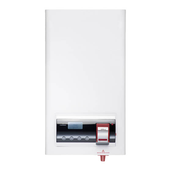
Clage-Zip Hydroboil Electronic
Instant boiling water
203362 Clage-Zip Hydroboil 3 Litre White
203361 Clage-Zip Hydroboil 3 Litre Stainless Steel
205362 Clage-Zip Hydroboil 5 Litre White
205361 Clage-Zip Hydroboil 5 Litre Stainless Steel
207362 Clage-Zip Hydroboil 7.5 Litre White
207361 Clage-Zip Hydroboil 7.5 Litre Stainless Steel
Clage-Zip Hydroboil Electronic - Installation & Operating Instructions - 87490 - June 2009
Installation and Operating Instructions
Page 1 of 16
Advertisement
Table of Contents

Related Manuals for Zip 203362 Clage-Zip Hydroboil


Summary of Contents for Zip 203362 Clage-Zip Hydroboil
- Page 1 205362 Clage-Zip Hydroboil 5 Litre White 205361 Clage-Zip Hydroboil 5 Litre Stainless Steel 207362 Clage-Zip Hydroboil 7.5 Litre White 207361 Clage-Zip Hydroboil 7.5 Litre Stainless Steel Clage-Zip Hydroboil Electronic - Installation & Operating Instructions - 87490 - June 2009 Page 1 of 16...
-
Page 2: Table Of Contents
All plumbing and electrical installations must comply with national regulatory requirements Page 2 of 16 Clage-Zip Hydroboil Electronic - Installation & Operating Instructions - 87490 - June 2009... -
Page 3: Read These Warnings First
A suitable form of water treatment may be necessary. All plumbing connections must be made in accordance with local regulations. The Clage-Zip Hydroboil instant boiling water heater is not intended for use by young children or infirm people without supervision. -
Page 4: Descaling
Note: If the water pressure is likely to exceed 7 bar, a 3.5 bar pressure reducing valve must be installed in the cold water supply line. Page 4 of 16 Clage-Zip Hydroboil Electronic - Installation & Operating Instructions - 87490 - June 2009... -
Page 5: Step 1 - Positioning
For exposed plumbing connection, connect the cold water inlet pipe from the base of the heater directly to the 15 mm or half-inch compression fittings with the nuts and olives provided. Elbow Spout detail Clage-Zip Hydroboil Electronic - Installation & Operating Instructions - 87490 - June 2009 Page 5 of 16... -
Page 6: Installation Procedures
Minimum - 0.7 bar, maximum - 7 bar. 250mm Warning: If pressure is likely to exceed 7 bar, a pressure limiting valve must be Wring installed in the cold water supply line. Clage-Zip recommends a valve rated at 45 mm 3.5 bar for this application. b) Venting... -
Page 7: Wall Mounting Template Dimensions
In order to help preserve our environment we ask that you dispose of this product correctly. Please contact your local city council for collection centre details Clage-Zip Hydroboil Electronic - Installation & Operating Instructions - 87490 - June 2009 Page 7 of 16... -
Page 8: Problem Solving
Warning- the water may be boiling - show extra care. 5. Test that in every instance the electrical resistance does not exceed 1 ohm. Page 8 of 16 Clage-Zip Hydroboil Electronic - Installation & Operating Instructions - 87490 - June 2009... -
Page 9: Tap Operating Procedures
Tap Operation Safety feature. Clage-Zip Hydroboil has a unique safety device designed to reduce the incidence of accidental operation of the tap. The tap can be “Locked” to prevent the Hydroboil from dispensing hot water In order to “lock” the tap, ensure the safety button is protruding from the right hand side of the control panel and the... -
Page 10: Operational Procedure Settings
Low Light Mode is indicated by the Low Light symbol on the LCD. When the unit actually enters energy saver mode it is indicated by the Sleep Mode Indicator on the LCD. Page 10 of 16 Clage-Zip Hydroboil Electronic - Installation & Operating Instructions - 87490 - June 2009... -
Page 11: Default Settings
In Normal operation mode the LCD will display as follows: Note: The BOILING WATER symbol is not displayed until the water reaches temperature. Clage-Zip Hydroboil Electronic - Installation & Operating Instructions - 87490 - June 2009 Page 11 of 16... -
Page 12: Configuration Mode
CHANGE FILTER icon will appear on the LCD after approximately 1minute. To clear the CHANGE FILTER icon, the user must re-enter Configuration, set the Filter Expiration Time to OFF and return to Normal Operation. Page 12 of 16 Clage-Zip Hydroboil Electronic - Installation & Operating Instructions - 87490 - June 2009... - Page 13 If no action is sensed on the CSS’s for 20 seconds, the unit will revert to Normal Mode. After SAT OFF-TIME 2 pressing either CSS1 or CSS4 will revert the unit to Normal Mode. Clage-Zip Hydroboil Electronic - Installation & Operating Instructions - 87490 - June 2009 Page 13 of 16...
-
Page 14: Spare Parts
90736 Insulation Kit 5Litre 90737 Insulation Kit 7.5Litre 90130 Clips for Curled Tank Kit 90744 PCB Kit Hydroboil 2006 90214 Sensor Sleep Mode Page 14 of 16 Clage-Zip Hydroboil Electronic - Installation & Operating Instructions - 87490 - June 2009... -
Page 15: Spare Parts
Spare Parts Clage-Zip Hydroboil Electronic - Installation & Operating Instructions - 87490 - June 2009 Page 15 of 16... -
Page 16: Contact Details
Images in this booklet have Telefax (04131) 8901-41 been modified and may not be true representations of the finished goods. Page 16 of 16 Clage-Zip Hydroboil Electronic - Installation & Operating Instructions - 87490 - June 2009.
Need help?
Do you have a question about the 203362 Clage-Zip Hydroboil and is the answer not in the manual?
Questions and answers