Table of Contents
Advertisement
Installation and Operating Instructions
®
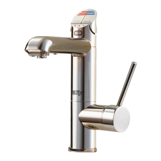
Zip HydroTap All-In-One
Filtered Boiling and Chilled water plus Hot and Cold water for kitchens and tea rooms.
This Installation Instruction covers the following HydroTap models:
Affix Model Number Label Here
89650UK
HydroTap Installation and Operating Instructions - 89650UK - August 2011 v1.02
Page 1 of 24
Advertisement
Table of Contents

Related Manuals for Zip HydroTap All-In-One BC 60/85A


Summary of Contents for Zip HydroTap All-In-One BC 60/85A
- Page 1 Installation and Operating Instructions ® Zip HydroTap All-In-One Filtered Boiling and Chilled water plus Hot and Cold water for kitchens and tea rooms. This Installation Instruction covers the following HydroTap models: Affix Model Number Label Here 89650UK HydroTap Installation and Operating Instructions - 89650UK - August 2011 v1.02...
-
Page 2: Check List
Check List Installation Checklist: Read the instructions. Note: Not all fittings are supplied with the appliance kit. Isolation valves are not supplied. Check the water pressure to determine if you require a pressure reduction valve or a flow restrictor added or removed from the kit. Check the water quality to determine if extra filtration will be required. -
Page 3: Table Of Contents
NOTE: Read all instructions and precautions before proceeding. If in doubt, or need further guidance, please call Zip on 0800 077 8302. Please leave these instructions with the end user after installation This unit must be installed in accordance with water supply byelaws, current IEE regulations and relevant local authority byelaws. -
Page 4: Product Description
Product Description Hydrotap All-In-One series are able to supply Boiling and Chilled water as well as Hot and Cold water, all from the same tap. The ‘AV’ series have their Boiling / Chilled / Hot outlets connected to the undersink (open vented) unit, Cold outlet conneted to the mains. The ‘A’... -
Page 5: Installation Requirements
Read These Warnings First (continued) ventilation. Auxiliary fan should always be fitted when supplied with large units. Make sure that the ventilation grilles of the undersink unit are not obstructed. ncluded in the installation pack are adhesive backed silicon buffers. If air vents are not installed Note: in the cupboards housing the HydroTap, the buffers must be placed on the inside edge of the cupboard door to create a slight gap ensuring a minimum airflow. -
Page 6: Models Covered By These Instructions
Installation Requirements (continued) • For AV models, cold water supply with a minimum working pressure of 2 bar (200 kPa) and a maximum working pressure of 7 bar (700 kPa) connected via an isolation valve. For all A models, cold and hot water supply with a minumum working pressure of 0.7 bar (70kpa) and a maximum working pressure of 7 bar (700 kPa). -
Page 7: Installation Procedure
Installation Procedure (continued) 2. Cut a 50mm hole in the bench / sink top. 3. Ensure the silicon O-Ring remains in place as this is the moisture seal against the bench / sink top. A light smearing of silicon sealant on the O-Ring will ensure a watertight fit. - Page 8 Step E - Connecting an external filter. (Not supplied as standard equipment). To combat the build up of lime scale, a high performance external filter kit may be ordered from your Zip service provider. Rear panel with external filter fittings Page 8 of 24...
- Page 9 6 bar. In this case a 3.5 bar (350 kPa) Pressure Reduction Valve will be required. - The rear of the unit is fitted with, 1/4” John Guest, inlet and outlet fittings, specifically for the Zip high performance filter kit. Fig.1...
- Page 10 Installation Procedure (continued) Step F- Testing and commissioning Vent line Boiling line Chilled line Filter Flush Mode The display screen will show which model you have. Have a bucket or similar container (not supplied) at the ready to hold a quantity of water that is ejected while the Filter Flush Mode is in operation.
-
Page 11: Operating The Mixer Tap
0.5ºC increments between 68º - 100ºC. Note: the Maximum setting of 100ºC is not recommended for normal use. Do not raise temperature above 98.5ºC without consulting Zip first to discuss the service ... -
Page 12: Mains Version Connections (Diagrams)
161.5 VENT OUTLET POSITION SILIC IN H TO T NOTE: BOILING IF THE FLOW RATE IS WATER CHILLED TOO FAST, CUT THE RED SILICONE UK 240V GPO WATER TUBE 75mm MINIMUM FROM THE BOTTOM OF THE BASE OF THE ALL-IN-ONE TAP. INSERT THE TEFLON RESTRICTOR ABOUT 20mm INTO THE UPPER SEGMENT OF THE RED SILICON TUBE WHICH... - Page 13 ALL IN ONE TAP-MAINS VERSION SILICONE HOSE FROM BOILING WATER TANK IN HYDROTAP UNIT TO TAP BRAIDED HOSE BH1 FROM MAINS WATER SUPPLY TO TAP BENCHTOP CABINET DOOR BRAIDED HOSE BH2 FROM DOMESTIC HOT WATER SUPPLY TO TAP 4mm BUFFER SILICONE HOSE FROM PAD TO ENSURE CHILLED WATER TANK...
-
Page 14: Vented Version Connections (Diagrams)
SILICONE HOSE FROM BOILING WATER TANK SILICONE HOSE FROM IN HYDROTAP UNIT TO TAP (Red) BOILING WATER TANK IN HYDRTAP UNIT TO TAP(Red) BRAIDED HOSE BH1 FROM MAINS WATER SUPPLY TO TAP(White Ring) MAIN SILICONE HOSE SUPP FROM STEAM VENT IN H/TAP UNIT(Clear) BH2 B BRAIDED HOSE BH2... - Page 15 ALL IN ONE TAP-VENTED VERSION BH1 WHITE MARKER BH3 RED MARKER SERVICE VALVE NS WATER BLUE MARKER REAR VIEW MAINS AMBIENT WATER SUPPLY (ISOLATION VALVE NOT SUPPLIED) HydroTap Installation and Operating Instructions - 89650UK - August 2011 v1.02 Page 15 of 24...
-
Page 16: External Filter Replacement
Internal Filter Replacement The Zip HydroTap notifies when filter replacement is due. The default setting is 6000 Ltrs, but this can be set in increments of 1000Ltr from 1000Ltr to 10000Ltrs. When a filter change is due, the Change Filter light will flash white once a second and remain so until reset. - Page 17 Press Adjust and it asks “are you sure”. Press Adjust again to Warning: If the Zip lock in the command. After approx 10 seconds it will default to the selected HydroTap is switched off for mode. a long period of time (e.g.
-
Page 18: Operating The Hydrotap
Operating the HydroTap (continued) Boiling Water Lever Boiling Filter Change Chilled Depressing the “Red” lever allows dispensing of Boiling water. Pulling up the Red lever allows the tap to operate in a “no-touch” mode. Water will flow from between 5 and 15 seconds (This is user adjustable). To reset, return the handle to the “Off”... -
Page 19: Setting The Energy Saver Timer
Setting the Energy Saver Timer Plus Adjust Button Menu Plus Button Minus Adjust Button Menu Minus Button Normal Operation Set Time Note: To change time, press either Menu or Menu button until Set Time is on the display Menu buttons screen. -
Page 20: Setting The Energy Saver Timer
Setting the Energy Saver Timer (continued) Activating ‘Sleep-when-it’s-dark’ feature This feature will automatically switch the unit into Sleep mode Option 1 when the ambient light falls below a set level. For this system to operate correctly the sensor in the tap head must be calibrated for it’s surroundings. Activation: This can only be achieved through the service mode. -
Page 21: Auxiliary Fan Attachment
Auxiliary Fan Attachment The HydroTap is equipped with an auxiliary fan connection point on the rear panel close to the cold water inlet / flex and plug area. The fan kit is available Auxiliary fan as a spare part. The fan operates in parallel with the Condenser fan helping connection to remove heat from the cupboard space. -
Page 22: Trouble Shooting
Trouble Shooting Symptom Possible Cause Solution No LED display, no tap head No power. Check power supply. lights or, no water when tap Plug is not located in power socket. Ensure power plug is correctly fitted and switch is levers are operated. turned ON. -
Page 23: Cleaning
Cleaning Do not use strong, corrosive, spray or abrasive cleaners. Clean with a soft cloth or brush and mild soap and water. Do not spray water over the tap as it may damage the low-voltage electronics. Undersink units must never be located near, or cleaned with water jets. End of Life Disposal The use of this crossed out wheeled bin logo indicates that this product needs to be disposed of separately to any other household waste. - Page 24 Furthermore, this warranty does not displace any statutory warranty, but, to the extent to which Zip is entitled to do so, the liability of Zip under any statutory warranty will be limited at Zip’s option to the replacement of the appliance or supply of equivalent appliance, the payment of the cost of replacing the appliance or acquiring an equivalent appliance, or the payment of the cost of having the appliance repaired or the repair of the appliance.
Need help?
Do you have a question about the HydroTap All-In-One BC 60/85A and is the answer not in the manual?
Questions and answers