
Related Manuals for SunStar KM-360J SERIES


Summary of Contents for SunStar KM-360J SERIES
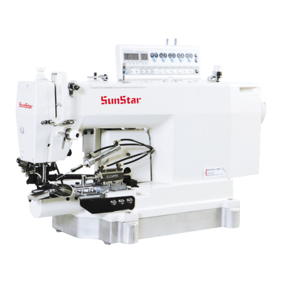
- Page 1 USER S MANUAL KM-360J SERIES High Speed 1-Needle, Needle Feed Bottom Hemming Sewing Machine (Mechanical Part)
- Page 2 1. Thank you for purchasing our product. Based on the rich expertise and experience accumulated in industrial sewing machine production, SUNSTAR will manufacture industrial sewing machines, which deliver more diverse functions, high performance, powerful operation, enhanced durability, and more sophisticated design to meet a number of user’s needs.
- Page 3 Machine Type MODEL KM ‐ 360 J ‐ Electronic puller & Attached with near Automatic trimming needle bar oscillating jean accessories Manual trimming system General Mechanical puller & needle bar oscillating system...
-
Page 4: Table Of Contents
Contents 1. Machine safety regulations --------------------------------------------------------------------- 1.1) Transporting machine ---------------------------------------------------------------------------- 6 1.2) Installing machine --------------------------------------------------------------------------------- 6 1.3) Repairing machine -------------------------------------------------------------------------------- 6 1.4) Operating machine ------------------------------------------------------------------------------- 7 1.5) Safety devices ------------------------------------------------------------------------------------- 7 1.6) Caution mark position ---------------------------------------------------------------------------- 8 1-7) Contents of marks -------------------------------------------------------------------------------- 8 2. - Page 5 6.4) Hook Lubrication Adjustment ----------------------------------------------------------------- 21 6.5) Puller (upper) Pressure Adjustment -------------------------------------------------------- 21 6.6) Presser Foot Pressure Adjustment --------------------------------------------------------- 21 6.7) Presser Foot Height Adjustment ------------------------------------------------------------ 22 6.8) Stitch Length Adjustment ---------------------------------------------------------------------- 22 6.9) Pneumatic Wiper Adjustment ---------------------------------------------------------------- 23 6.10) Trimmer Cam Adjustment ------------------------------------------------------------------- 23 6.11) Blade Position Adjustment ------------------------------------------------------------------ 23 6.12) Thread Take-up Lever Adjustment -------------------------------------------------------- 24 7.
-
Page 6: Machine Safety Regulations
Machine safety regulations Safety instructions on this manual are defined as Danger, Warning and Caution. If you do not follow the instructoins, physical injuries and machine damages might be occurred. Danger : This indication should be observed definitely. If not, there will be a danger during the installation, conveyance and maintenance of the machine. -
Page 7: Operating Machine
1.4) Operating KM-360J series were designed as industrial sewing machines to conduct bottom hemming on machine fabric and similar materials. Observe the following instructions during machine operation. ⓐ Read through this manual carefully and completely before operating the machine. ⓑ Wear proper clothes for work. -
Page 8: Caution Mark Position
1.6) Caution mark Caution mark is attached on the machine for safety. When you operate the machine, follow the directions on the mark. position CAUTION 주 의 Do not operate without finger guard and safety devices. Before threading, changing bobbin and needle, cleaning etc. switch off main switch. -
Page 9: Machine Specifications
Machine Specifications Model Name KM-360J-7E KM-360J-7M KM-360J-M Jeans bottom hemming (for heavy materials) Lubrication Automatic lubrication Sewing Speed Up to 4,000 spm Stitch Length 2~5mm 2~4.2mm Needle Bar Stroke 34.6mm Thread Take-up Lever Stroke 70.8mm Needle DP×5 SERV 7 110 Hook Rotary large hook (2x) Pants Hem Size... -
Page 10: Machine Parts
Machine Parts 3.1) Parts Name ⑭ ⑬ ⑫ ④ ① ⒔ ⒕ ⑨ ⑮ ② ③ ⑧ ⑪ ⒖ ⑩ ⑥ ⒃ ⑤ ⑦ ① Thread winder ⑧ Power switch ② Pneumatic wiper ⑨ Oil window ③ Presser bar lifter ⑩... -
Page 11: Machine Installation
Machine Installation 4.1) Installation Environment A. Do not use the machine if the voltage is below or above 10% of the rated voltage to prevent error-driven accidents. B. Check the required air pressure for the devices using air pressure such as air cylinder to prevent error-driven accidents. C. -
Page 12: Machine Placement On The Table
4.3) Machine Placement on the Table A. Fix the control box ① to the table. ② ① [Fig. 1] B. Put the oil fan ① on the marked place and fix the bed hinge bracket② to the holes. ② ① [Fig. -
Page 13: Part Assembly
E. Install the motor and fully loosen the fixing nuts ①, ②. Then, tension is generated around the belt ④ due to the weight of the motor ③. Fasten the fixing nut ① first and tightly fasten the fixing nut ② (KM-360-M). ④... - Page 14 C. Install the thread stand ② on the table ①. ② D. Hammer the head supporting stick ③ into the table. ③ ① [Fig. 8] Make sure the head supporting stick completely inserted into the table. Otherwise, when the sewing machine head is pushed backward, it is not stable and dangerous. Caution E.
-
Page 15: Preparation Before Use
Preparation Before Use 5.1) Oil Supply ① A. Remove the rubber cap ① on the arm face and supply oil through a funnel ②. ② B. Oil should be supplied until the scale is located between the upper and lower limit of the oil gauge ③. ③... -
Page 16: Bobbin Case Insertion And Disposal
5.4) Bobbin Case Insertion and Removal Open the hook cover and push the bobbin into the hook with the bobbin case handle held until the click sound is heard. ① ② [Fig. 14] If the bobbin case is not properly placed, thread entanglement or bobbin ejection might result during machine operation. -
Page 17: Upper Thread Tension Adjustment
5.6) Upper Thread Tension Adjustment Turn off the power switch when inserting or removing the bobbin case. If the pedal is mistakenly stepped, it may operate the sewing machine, causing injury to user. Caution Sewing Type Cause Corrective Action Evenly created good stitch If the upper thread tension is too weak or the Strengthen the upper thread tension or weaken lower thread tension is too strong... -
Page 18: Remaining Thread Adjustment After Trimming
5.7) Remaining Thread Adjustment After Trimming A. During trimming, the tension of the main thread adjuster is not involved, while the tension of the auxiliary thread adjusting device ① plays a role. Stronger B. The standard remaining thread length after trimming is Weaker 35~40mm. - Page 19 C. Pull up the adjusting handle at the upper part of the filter regulator and turn it clockwise as in the figure. This increases pressure. If it is turned counter-clockwise, pressure decreases. Adjust the pressure to the appropriate level of 0.49~0.54MPa (5~5.5Kgf/cm ) as marked on the pressure gauge and then return and settle the adjusting handle.
-
Page 20: Maintenance
Maintenance 6.1) Needle Bar Height Adjustment When the needle bar ① is at the lowest position, set the carved line ⓐ of the needle bar ① to meet the bottom of the oil rejecter cover ②. ② A. Turn the pulley and place the needle bar ① at the lowest ⓐ... -
Page 21: Hook Lubrication Adjustment
6.4) Hook Lubrication Adjustment Hook A. Lubrication Volume Check a. Conduct idle operation for some 3 minutes (at an appropriate speed). Place the lubrication test sheet as in the figure and operate the machine for 5 seconds to check lubrication. Check oil volume sprayed to the Lubrication test sheet sheet. -
Page 22: Presser Foot Height Adjustment
6.7) Presser Foot Height Adjustment ④ When the presser bar lifter ② is lifted, the presser foot ① is ③ normally lifted 4mm. At this time, the distance between the rollers (up) ⑥ and (down) ⑦ is 5mm. A. Loosen the nut ③ and unfasten the pressure adjusting ⑧... -
Page 23: Pneumatic Wiper Adjustment
6.9) Pneumatic Wiper Adjustment A. Release air pressure. B. Turn the pulley to place the thread take-up lever at the highest position. ③ C. Pull the wiper ① and loosen the nut ②. Adjust the wiper position as in the figure and fasten the nut ②. D. -
Page 24: Thread Take-Up Lever Adjustment
6.12) Thread Take-up Lever Adjustment A. Loosen the nut ①. B. Turn the adjusting screw ② to set the distance between the thread release lever roller ③ and the trimmer cam at ③ 0.5mm. ① C. Fasten the nut ①. ②... -
Page 25: Causes Of Troubles And Troubleshooting
Causes of troubles and troubleshooting Symptom Checkpoints Root cause Corrective action Direction and height of Needle is inserted into wrong Reinsert the needle correctly. needle direction. Needle Needle is bent. Replace the needle. Bad timing of feed dog. Adjust the timing of feed dog. Ascending level of needle Bad timing of needle and hook. - Page 26 Symptom Checkpoints Root cause Corrective action Too tight upper thread tension. Reduce tension of upper thread. Upper thread does not sink. Too loose lower thread tension. Increase tension of lower thread. Too weak upper thread tension. Increase upper thread tension. Lower thread does not sink.
-
Page 27: Km-360J-7M (Type A)
Table Drawings 8.1) KM-360J-7M (Type A) -
Page 28: Km-360J-7M (Type B)
8.2) KM-360J-7M (Type B) -
Page 29: Km-360J-7M (Type C)
8.3) KM-360J-7M (Type C) -
Page 30: Pneumatic Circuit Diagram
Pneumatic Circuit Diagram 9.1) KM-360J-7M(E)
Need help?
Do you have a question about the KM-360J SERIES and is the answer not in the manual?
Questions and answers