High speed, two needle, drop
feed, needle feed, sewing
machine with automatic thread
trimmer.
high speed, two needle, drop
feed, needle feed, split needle
bar lock stitch m/c with
automatic thread trimmer (35 pages)
High speed post bed, 1-needle needle feed lock stitch machine with thread trimmer for reinforcement stitch of jean (38 pages)
Summary of Contents for SunStar KM-250 Series
Page 1
USER’S MANUAL 
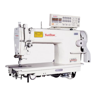
KM-250/KM-350 Series High-Speed, 1-Needle, Drop-Feed Automatic Thread Trimmer High-Speed, 1-Needle, Drop-Feed, Needle-Feed Automatic Thread Trimmer Keystone Sewing Machine Company, Inc. 833 N 2nd Street, Philadelphia, PA 19123 USA KM-506/KM-530 Series 215/922.6900 High-Speed 1-Needle, Drop-Feed info@keysew.com Knife-Attached Automatic Thread www.keysew.com Trimmer High-Speed, 1-Needle, Drop-Feed,...
Page 2
1. Thank you for purchasing our product. Based on the rich expertise and experience accumulated in industrial sewing machine production, SUNSTAR will manufacture industrial sewing machines, which deliver more diverse functions, high performance, powerful operation, enhanced durability, and more sophisticated design to meet a number of user’s needs.
Safety rules for machines Safety labels in the manual are categorized into danger, warning and caution. Failure to follow the safety rules may result in physical injuries or mechanical damages. The safety labels and symbols are defined as follows. [ The meaning of the safety marks ] Danger Instructions here shall be observed strictly.
Page 5
No part of the machine or specifications may be modified without prior consultation with our company. Any such modification could risk safe operation of the machine. In case of repair, replace only with standard OEM parts from SunStar. After repair, put safety covers back on the machine.
Page 6
1-4) Machine KM-250 Series are intended to be used for industrial purposes for sewing textiles and operation other similar materials. Carefully study the following instructions before operating the machine. Read the manual thoroughly and understand the instructions fully before use.
Page 7
1-6) Location of Caution is attached on the machine for safety. Read the directions of caution caution mark carefully before running the machine. [Location of caution mark] 1-7) Contents of caution Caution Keystone Sewing Machine Company, Inc.
Installation Warning The machine must be installed by a trained technician only. Any electrical wiring must be performed by a qualified technician or agent. The machines weigh over 33 kg. As such, two or more people should carry out the installation. Plug in only after the installation is complete.
3) Resistance box for knee-lifting solenoid (KM- -7N) (1) Installation Automatic knee-lifting solenoid A. Attach the resistance box around the motor under the table. B. Connect the connector from the solenoid to the resistance Resistance box box as shown in Fig. 3, and then connect the line from the resistance box to the control box.
(2) Lubricating the oil fan A. Fill the lubricant up to the HIGH mark. (See Fig.5.) B. The lubricant must be SUNSTAR s oil provided exclusively for industrial sewing machines or SHELL s Tellus C10. C. If the oil in use is down to the LOW mark, fill in to HIGH immediately.
(2) Installing manual knee-lifter A. Use four fixing screws to attach the bracket onto the program unit . B. Fasten the bracket tightly using the three fixing screws in the back lid of the machine. (See Fig. 8) [Fig.8] 7) Belt Cover (1) Use the clamp screws in the machine body and the washer...
8) Location Detector Assembly and Adjustment (1) Installing the location detector A. Installing on the servo motor (in-built location detector) A location detector sensor is attached to the back side of the arm. The appropriate clearance between the location detector and the pulley is 0.5mm. (See Fig. 11) [Fig.11] (2) Installing the 470 motor After assembling the parts in the numbered order as in Fig.
(2) For 470 Motors Turn the pulley manually to position the needle bar at the lowest point about to move back up. Then, loosen the fixed screws on the film as in Fig. 12 and align the DOWN film with the film adjustment baseline and the sensor housing baseline as in Fig.
Control and Adjustment of the Sewing Machine Caution Always turn off the power when mounting a needle. If the operator mistakenly steps on the pedal while the power is on, the machine will start automatically and can result in physical injuries. When using clutch motor, be aware that the motor will continue to rotate for a while even after the power is switched off due to inertia.
Caution When checking the oil level in the hook, keep your hands or oil flow checking paper away from any moving parts including transfer tools, to avoid injury. 5) Lubrication Adjustment of Hook (1) Checking the oil supply level of hook Hook A.
Start to work on the sewing machine only after the motor has come to a complete stop. 7) Routing Upper Thread Place the thread take-up lever at the highest position and route the upper thread in the order indicated in Figures 24 and 25. KM-250 Series KM-350 Series [Fig. 24] [Fig. 25]...
8) Upper Thread Adjustment When the upper thread is weak (1) Main thread adjustment device The tension of the upper thread gets tighter if the tension adjusting nut as in Fig. 26 is turned in a clockwise When the upper thread is strong direction and it gets looser when turned in the opposite direction.
Caution After disassembling and adjusting a safety device, always place it back to the original position and check whether it functions as intended. Use both hands when pushing the machine backward or returning it to the original position. Due to the weight of the machine, your hand can get stuck in the machine if you should slip. When adjusting the machine with the switch on, be sure to pay extreme caution.
11) Stitch Length Adjustment As is shown in Fig. 31, the number marked by the stitch adjusting dial signifies the stitch length in mm units. Move the dial sideways to set it to the desired stitch length (Turn it in clockwise direction and the stitch length will decrease while turning it counterclockwise will increase the stitch length.) [Fig.
13) Feed Cam Adjustment The timing of the feed dog and needle is adjusted by turning the feed cam up and down. When the pulley is turned such that the feed dog is lowered so that the top of the feed dog is aligned with the top of the needle plate, the lower needle hole will come in direct line with the top of the feed dog.
15) Timing Adjustment of Trimmer (1) Turn the pulley manually and align the red carved sign on the pulley and the carved sign on the arm. (2) Separate the return spring . White Dot (Synchronization color point) [Fig. 36] (3) Push the trimming lever so that the thread trimming knife on the hill of the movable knife is about 1~1.5mm more...
16) Tension Adjustment of Fixed Blade Wrench Box First, loosen the fixed blade tension adjusting nut with a wrench box and then loosen the tension adjusting screw . As in Fig. 39, adjust the tension adjusting screw of the fixed Movable Knife blade when the movable knife-edge meets the fixed knife- edge.
(2) If the trimming was done manually, stop the machine when the edge of the fixed knife meets the bobbin Bobbin Catcher Adjustment Baseline catcher adjustment baseline that is marked on the top. Loosen the bobbin catcher fixing screw and adjust the bobbin catcher so that the contact surface of the bobbin catcher lightly touches the center of the protruding...
21) Knife Adjustment (KM-506-7/KM-530-7 Series) (1) Adjusting the height of the knife Area A [Fig. 48] A. The knife is operated by the lever at the center of the sewing machine. If the lever is pulled down, the cutting and sewing of the material can be done simultaneously. If the lever is pulled up, sewing is done without cutting.
22) Use of Chip Discharge Guide and Auxiliary Needle Plate (KM-506/530 Series) (1) When Cutting and Sewing Simultaneously When cutting and sewing are done at the same time, attach the chip discharge guide , which is provided in the accessory box, to the auxiliary needle plate with fixing screws .
Page 28
(2) Assembly A. Replace the chip discharge guide (lower) with the one fit for the desired cutting width and fix it with the auxiliary screw on the auxiliary needle plate . B. Fix the auxiliary needle plate using two fixing screws on the bed.
Cause of troubles and troubleshooting 1) Sewing machine troubleshooting Symptom Checkpoints Root cause Corrective action Needle is inserted into wrong position. Direction and height of needle Reinsert the needle correctly. Needle Needle is bent. Change the needle. Bad timing of feed dog. Adjust the timing of feed dog.
Page 30
Symptom Checkpoints Root cause Corrective action Too tight upper thread tension. Reduce tension of upper thread. Upper thread does not sink. Too loose lower thread tension. Increase tension of lower thread. Too weak upper thread tension. Too strong lower thread tension. Lower thread does not sink.
Page 31
MEMO Keystone Sewing Machine Company, Inc.