
Related Manuals for SunStar KM-2070P SERIES


Summary of Contents for SunStar KM-2070P SERIES
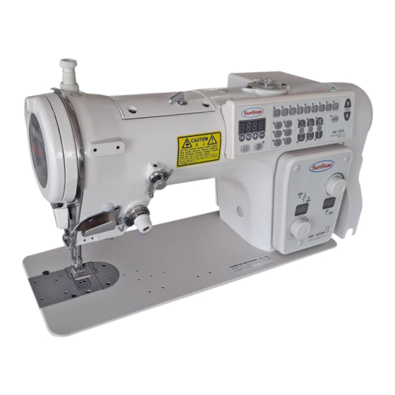
- Page 1 USER S MANUAL KM-2070P SERIES Electronically Controlled 1-Needle ZigZag Lock Stitch Machine Electronic Control Part...
- Page 2 1. Thank you for purchasing our product. Based on the rich expertise and experience accumulated in industrial sewing machine production, SUNSTAR will manufacture industrial sewing machines, which deliver more diverse functions, high performance, powerful operation, enhanced durability, and more sophisticated design to meet a number of user’s needs.
-
Page 3: Table Of Contents
Contents 1. Internal Structure of Control Box 2. Connection of Power Voltage and Control Box Cable 1) Power Voltage and Power Code Connection 2) Cable Connection to Control Box 3. Using Operation Panel and Sewing 1) Operation Panel and key Functions 2) Pattern Setting Method 3) Sewing Method of Left/Right Scallop 4) Sewing Method of Left/Right Blind... -
Page 4: Internal Structure Of Control Box
Internal Structure of Control Box [2070P CONTROL BOX] Cooling Fan Step Motor Driving Board Digital Board Servo Motor Driving Board Transformer Power Board... -
Page 5: Connection Of Power Voltage And Control Box Cable
Connection of Power Voltage and Control Box Cable 1) Power Voltage and Power Code Connection (1) Voltage Specification Match the indication of voltage to specification of power code and connect the cable. 1. Must not use on condition that voltage specification is different. 2. -
Page 6: Cable Connection To Control Box
2) Cable Connection to Control Box A. Internal Wiring of Control Box (Common in all types) Step Motor Driving Board Cooling Fan 14. Step Motor Driving Signal Cable 15. Servo Motor Driving Signal Cable Digital Board 16. Servo Motor Auxiliay Signal Cable Servo Motor Driving Board 21. -
Page 7: Using Operation Panel And Sewing
Using Operation Panel and Sewing 1) Operation Panel and Key Function ① ② ③ ④ ⑤ ⑥ ⑦ ⑧ ⑨ ⒗ (27) (21) ⒖ (22) (25) (23) (24) (26) ⑩ ⑫ ⑭ ⑮ ⑬ ⑪ ⒃ ⒔ ⒕ ⑧ Right-blind pattern key ①... -
Page 8: Pattern Setting Method
2) Pattern Setting Method ■ Operation Panel Indication Status ■ Operation Order 1. Turn on the power. <Initial Setting Status of Operation Panel> Indication Device (Unit: 0.1mm) ZigZag-Width Indication (8mm) Indication lamp of 2 point pattern Turned On Indication lamp of needle down stop Turned On Presser Foot Indication Lamp Turned On... - Page 9 ■ Basic Pattern Number and Shape Status of Indication Device Pattern No. Pattern Name Straight Line Pattern 2 point (standard) zigzag pattern 3 point (2 step) zigzag pattern 4 point (3 step) zigzag pattern 5 - 1 1(24 Stitches) 2(12 Stitches) 5 - 2 Left Scallop pattern...
-
Page 10: Sewing Method Of Left/Right Scallop
3) Sewing Method of Left/Right Scallop Ex) Selection shape No. 3 of Left scallop Pattern ■ Operation Panel Indication Status ■ Operation Order 1. Press left scallop key. ·Indication lamp of left scallop turns on. At the same time, Power On Start pattern number and shape number are displayed on the Indication Device indication device and after a moment, zigzag-width is... -
Page 11: Sewing Method Of Left/Right Blind
4) Sewing Method of Left/Right Blind Ex) 5 Stitch Setting of Left Blind ■ Indication Status of Operation Panel ■ Operation Order 1. Press left blind key. ·Left blind indication lamp turns on and pattern number and Power On Status stitch number for left blind are displayed on the indication Indication Device device at the same time and after a moment, zigzag-width... -
Page 12: Sewing Method Of Left/Right L-Stitch
5) Sewing Method of Left/Right L-Stitch Ex) Set up five stitches for left L-stitch and repeat two times. ■ Operation Panel Indication Status ■ Operation Order 1. Press Left Blind key. Power On Start [Indication Device] The left blind display lamp turns on, its pattern number and the number of stitches are displayed on the indication device, then the zigzag-width is displayed. -
Page 13: Zigzag Width (Max. Zigzag-Width: 10Mm)
6) ZigZag Width ( Max. zigzag-width : 10mm ) Unit) 0.1mm ■ Indication Status of Operation Panel ■ Operation Order ※ Status of Power On ZigZag-width is displayed on the indication device Select the desired pattern shape. ( Lamp of the selected pattern turns on. Ex: pattern 5) as above picture. -
Page 14: Sewing Speed
7) Sewing Speed ■ Indication Status of Operation Panel ■ Operation Order ·Press speed increase key (arrow direction is up) in order to increase the speed and press speed decrease key (arrow Power On Status direction is down) in order to decrease the speed. Indication device ·The changed speed is on the monitor and then automatically number of with appears. -
Page 15: Using Method Of Start Condence
8) Using method of start condence Ex) It is the example of pattern 3 with zigzag-width of 6mm. ■ Indication statas of Operation Panel ■ Operation Order 1. Press start condense key on condition that power in on. Power On Status Lamp of start condense turn on, and A side stitch Indication Device number of start condense is displayed on the indication... - Page 16 Width of start condense ■ Changing stitch number and width of start condense Start point -Sewing type of start condense A side stitch number of start condense Status of Sewing B side stitch number of start condense ■ Operation order. 1.
-
Page 17: Using Method Of End Condense
9) Using Method of End Condense Ex) It is the example of pattern 3 with ZigZag-width of 6mm. ■ Indication Status of Operation Panel ■ Operation Order 1. Press end condense key on condition that power is on. Indication lamp of end condense turns on and C side stitch number of end condense is displayed on the indication Power On Status device. - Page 18 ■ Changing stitch number and width of end condense. Sewing type of end condense. end condense stitch number (C side) status of sewing end condense, width end condense stitch number (D side) ■ Operation Order 1. Press and condense key on condition that power is on. Power On Status [indication device] Indication lamp of end condense turns on and C side stitch...
-
Page 19: Setting Of Base-Line
10) Setting of Base-Line - Location of base-line is set to ‘0’ at the moment of shipping from factory. - Lacation of base-line can be set up to 4[mm] in the left and right from on the origin. ■ Indication Status of Operation Panel ■... - Page 20 ■ Considerations to set location of base line In the sewing pattern as figure [a], moving the location of base line 2mm (L-20) to the left, it is sewn as shown in the figure [b]. When moving location of base line 3mm (L-30) to the left and setting zigzag width of 4mm, due to exceeds the sewing range as shown in the figure [c], so zigzag width is automatically set to the maximum range not exceeding the range and sewing is done such.
-
Page 21: Left/Right Stop Location Of Needle
11) Left/Right Stop Location of Needle ■ Indication Status of Operation Panel ■ Operation Order ※ It is the example by 2 point pattern(standard zigzag, pattern Power On number 2 ) width of 8[mm]. Indication device 1. Press Needle Left/Right stop key on condition that power is on. - Page 22 Ex) In case of right stop setting Pedal Neutral Location (Sewing Stop) Stop Stop Stop <2point pattern> <4point pattern> <right scallop > [ Fig. 3-2 ] Example of Needle Right Stop Setting <Note> Unless set the left/right stop location of needle, it can stop anywhere. In case of straight-line pattern and blind pattern, left/right stop location of needle is not reflected.
-
Page 23: Up/Down Stop Of Needle
12) Up/Down Stop of Needle - This setting is used to check location of sewing material correctly or it is usefully used for reverse function(mirror) and name stitch sewing. Setting method is to turn on the indication lamp of down stop by pressing up/down stop key of needle. It is selected to initial value of down stop. -
Page 24: Reverse (Mirror) Function
14) Reverse (mirror) Function ■ Indication Status of Operation Panel ■ Operation Order ※ Status that power is on. ※ Zigzag width displayed on the indication device. Power On Status Indication Device ※ Pattern was set to left scallop No.3 in advance. ※... - Page 25 ■ Example applied use of reverse function Direction converting point Status that did not press reverse button In case of reverse function Off [In case that did not use reverse function] Direction converting point Direction converting point Status that pressed reverse Status that button pressed reverse...
-
Page 26: Name Stitch
15) Name Stitch ■ Indication Status of Operation Panel ■ Operation Order 1. Press name stitch key on condition that power is on. ( confirm the set stitch number ) Indication lamp of name stitch turns on. Power On Status pressing one time : display vertical stitch number on the Indication Device indication device ( Ex : E-... - Page 27 ■ Change of vertical stitch number(E) and horizontal stitch number (F) of name stitch Power On Status - pattern number : 2 point pattern Indication Device - zigzag width : 6mm 1. Press name stitch key on condition that power is on. Indication lamp of name stitch turns on and vertical stitch number is displayed on the indication device.
-
Page 28: Deciding Presser Foot Up/Down Location
AUTO on : automatic thread trimming Thread Trimming ※ Sew is possible as much as the set ※ If AUTO lamp is ON, the machine stitch number and thread automatically executes thread trimming trimming is possible as well. at the completing point of sewing. [ a ] [ b ] E (vertical stitch number) sewing and name stitch sewing... -
Page 29: Using Reverse Feed Control Lever And Using Reverse Button(A Button)
20) Using Reverse Feed Control Lever and Using Reverse Button(A Button) [ forward condense [ Backward condense Sewing Start sewing function ] sewing function ] Practical sewing state Sewing Sewing Back tack Switch Feed reverse Reverse Feed Button is on Adjustment Dial feed lever [ condense →... -
Page 30: Rom Pattern (Use Pattern) Input Method
21) Rom Pattern (Use Pattern) Input Method ■ Indication Status of Operation Panel ■ Operation Order 1. Press PARA/SET key. Power On Indication Device Indication device blinks. 2. Press ROM pattern key. ROM pattern number and pattern shape number are displayed on the indication device. -
Page 31: Method Of Setting The Starting Point
23) Method of Setting the Starting Point KM-2070P B/T Starting Point Setting Flow As in the existing KM-2070P model, perform the setting of machine and install the control box. 1) Install the B/T motor and starting point sensor. 2) Connect the B/T motor and the starting point sensor cable. 3) Install the Dial O/P and connect the cable to the digital B/D. -
Page 32: Error Indications And Action Plan
Error Indications and Action Plan Content Check error error code ·Check badness of connector connection X origin check error Er06 ·Check badness of X origin sensor ·Check badness of connector connection Y origin check error Er66 ·Check badness of Y origin sensor ·Input pattern data editing Pattern prohibit error Er09... -
Page 33: Others
Others 1) Initialization of Machine 1. Turn on the power with pressing needle Up/Down key, presser foot up/down key and thread trimming/wiper key. 2. Indication device displays I n I t and after a moment, width is displayed. Then, initialization is completed. 2) Inertia Tuning 1. -
Page 34: Machine Test Function
4) Machine Test Function ■ Test Mode and Description < Operation Method > 1. Turn on the power with pressing zigzag-width key and start condense key. Indication device is displayed “ tESt” and after a moment, returns to test function mode. Indication device displays “t-01”... - Page 35 (4) Pulley Location (Encoder) Test Function 1. After selection test mode, make” t-04” to be displayed. Set the mode by pressing half-stitch key. 2. Turning by hands as shown in the figure, encoder angle is displayed on the indication device. Encoder angle 3.
- Page 36 (8) Aux In Test Function 1. After selection test mode, make” t-08” to be displayed. Set the mode by pressing half-stitch key. 2. Pressing knee-lifter key, indication lamp of end condense turns on or turn off, and pressing reverse switch(A button), lamp of needle down stop turns on or turns off.
-
Page 37: Parameter Changing Method And Classification
5) Parameter Changing Method and Classification (1) General Sewing related Parameter Number (A Group) ※ Operate by pressing N1 key after turning on the power pressing PARA/SET key. Select desired number, press straight-line pattern key and change parameter value. Then, store the changed value by pressing straight-line pattern key again. Function and Description Setting Scope Shipping Status... - Page 38 (2) Servo Motor related Parameter Number (B Group) ※ Operate by pressing N2 key after turning on the power pressing PARA/SET key. Select desired number, press straight-line pattern key and change parameter value. Then, store the changed value by pressing straight-line pattern key again. Function and Description Function Name Setting Scope Shipping Status Unit,Remarks Location detecting speed to stop...
- Page 39 ※ Description of Shade part Stop Rapid Speed reduction command area by pedal ■B-04 (DIST1) : It is the value indication location that rapid speed reduction is completed at stop and though stable rapid speed reduction is available as much as the value is bigger, but final stop section gets long. ■B-08 (KC2) : It can acquire by inertia tuning and if the value gets bigger, pursuit for speed gets slow.
-
Page 40: Exchanging The Fuse
6) Exchanging the fuse To prevent from electric shade, turn off the power and wait 5 minutes, then open the cover. Be sure to turn off power and exchange into the fuse of the designated quantity after opening the cover of control box.
Need help?
Do you have a question about the KM-2070P SERIES and is the answer not in the manual?
Questions and answers
How to speed lock opend
@Suresh Suresh
The SunStar KM-2070P SERIES has a maximum sewing speed of 5,000 stitches per minute (spm), but it is set to 4,000 spm at the time of shipment. To adjust the speed, use the operation panel to modify the speed settings according to the machine's user manual instructions.
This answer is automatically generated