Table of Contents
Advertisement
S S U U N N S S T T A A R R M M A A C C H H I I N N E E R R Y Y C C O O . . , , L L T T D D . .
USER'S
MANUAL
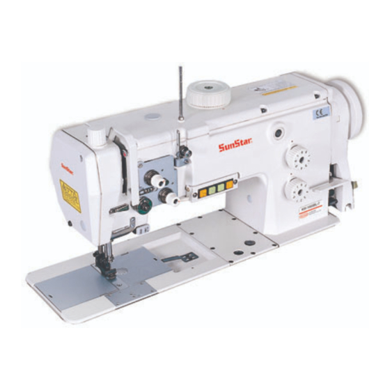
KM-1060BL Series
KM-1060BL
High Speed, 1-Needle, Unison Feed
Lock Stitch Machine
KM-1060BL-7
High Speed, 1-Needle, Unison Feed Lock Stitch
Machine with an Automatic Thread Trimmer
KM-1062BL
High Speed, 2-Needle, Unison Feed
Lock Stitch Machine
KM-1062BL-7
High Speed, 2-Needle, Unison Feed Lock Stitch
Machine with an Automatic Thread Trimmer
1) FOR PROPER AND CONVENIENT USE OF
THE MACHINE, THOROUGH READ THIS
MANUAL BEFORE USE.
2) KEEP THIS MANUAL IN A SAFE PLACE
FOR FUTURE REFERENCE IN CASE THE
MACHINE BREAKS DOWN.
M M M M E E - - 0 0 5 5 0 0 6 6 2 2 9 9
Advertisement
Table of Contents

Related Manuals for SunStar KM-1060BL


Summary of Contents for SunStar KM-1060BL
- Page 1 USER’S MANUAL KM-1060BL Series KM-1060BL High Speed, 1-Needle, Unison Feed Lock Stitch Machine KM-1060BL-7 High Speed, 1-Needle, Unison Feed Lock Stitch Machine with an Automatic Thread Trimmer KM-1062BL High Speed, 2-Needle, Unison Feed Lock Stitch Machine KM-1062BL-7 High Speed, 2-Needle, Unison Feed Lock Stitch...
- Page 2 1. Thank you for purchasing our product. Based on the rich expertise and experience accumulated in industrial sewing machine production, SUNSTAR will manufacture industrial sewing machines, which deliver more diverse functions, high performance, powerful operation, enhanced durability, and more sophisticated design to meet a number of user’s needs.
-
Page 3: Table Of Contents
Contents Safety rules for machines 1. Specifications 1) Sewing machine 2) Motor 3) Peripheral automation devices (optional) 2. Installation 1) Oil fan 2) Machine head 3) Belt tension adjuster 4) Belt cover 5) Program unit (thread trimming type) 6) Air pressure-related parts and functions (thread trimming type) 7) Thread spool stand assembly 8) Knee-lifting pad (thread non-trimming type) 9) Lubrication check... -
Page 4: Safety Rules For Machines
Safety rules for machines Safety labels in the manual are categorized into danger, warning and caution. Failure to follow the safety rules may result in physical injuries or mechanical damages. The safety labels and symbols are defined as follows. The meaning of the safety marks Danger Instructions here shall be observed strictly. - Page 5 ⓑ No part of the machine or specifications may be modified without prior consultation with our company. Any such modification could risk safe operation of the machine. Danger ⓒ In case of repair, replace only with standard OEM parts from SunStar. ⓓ After repair, put safety covers back on the machine.
- Page 6 KM-1060BL Series are intended to be used for industrial purposes for sewing textiles and 1-4) Machine operation other similar materials. Carefully study the following instructions before operating the machine. ⓐ Read the manual thoroughly and understand the instructions fully before use.
- Page 7 1-6) Location of caution mark “Caution”is attached on the machine for safety. Read the directions of “caution”carefully before running the machine. [Location of caution mark] CAUTION 경 고 Do not operate without finger guard and safety devices. Before threading, changing bobbin and needle, cleaning etc.
-
Page 8: Specifications
Specifications 1) Sewing machine Description KM-1060BL-7 (trimming type) KM-1060BL KM-1062BL (Trimming type) KM-1062BL Application Medium heavy to very heavy material Maximum stitch length Stroke distance of needle bar 33.8mm Lifting amount of presser foot Maximum of 7 mm Needle type... -
Page 9: Installation
Installation Warning ▶The machine must be installed by a trained technician only. ▶Any electrical wiring must be performed by a qualified technician or agent. ▶The machines weigh over 52 kg. As such, two or more people should carry out the installation. ▶Plug in only after the installation is complete. -
Page 10: Belt Tension Adjuster
3) Belt tension adjuster After installing the motor③, slacken both fixing nuts① and② just enough to give adequate tension to belt④. Firmly tighten the fixing nuts① and② consecutively. ④ ① ③ ② [ Fig. 4) Belt cover B. After placing the belt cover “B” ② into the belt cover “A” A. -
Page 11: Air Pressure-Related Parts And Functions (Thread Trimming Type)
Caution ▶When it becomes necessary to regulate the machine with the power on or with the air injected, exercise extreme caution for safety. ▶Set the air pressure at 0.5 Mpa. 6) Air pressure-related parts and functions (thread trimming type) A. Installation a) Use a screw to fix the pneumatic unit①... -
Page 12: Thread Spool Stand Assembly
B. Adjustment of pneumatic pressure ② a. Adjust the pressure by pulling knob② from pneumatic filter①. b. Control the pneumatic pressure at 0.49 MPa (5kgf/cm and put the knob② back to its original position.. ① [ Fig. 8 ] 7) Thread spool stand assembly Secure the thread spool stand assembly①... -
Page 13: Lubrication Check
Caution ▶ Plug in only after oil supply is finished. If the operator mistakenly steps on the pedal with the plug in, the machine will start automatically and can cause severe injuries. ▶ When handling lubricants, wear protective glasses or gloves to avoid contact with your eyes or skin. -
Page 14: Check For Stop Position Of The Sewing Machine (Thread Trimming Type)
C. Hook part Open the slide plate (right)① to add the sewing machine oil into an arrow-pointed position. Close the slide plate① after oiling. ① [ Fig. 13 ] D. Oil window check After applying oil to each friction parts, turn on the main switch and operate the machine at a low speed for five minutes to check the oil flow in the oil hose passing the oil window. -
Page 15: Back Tack Button (Thread Trimming Type)
A. Check for up-stop position of needle bar The up-stop position of needle bar is where the take-up lever① stops 2mm off of its highest position. For adjustment, move the magnetic holder② built in a carved ② N.U. sign of the pulley to the left and right. ①... -
Page 16: Check For Switch Functions (Thread Trimming Type)
12) Check for switch functions (thread trimming type) : Conversion switch for presser foot lifting level ① - When you press this switch, the light will come on. The lifting amount of the presser foot will automatically change to the maximum 7 mm regardless of what the set-up data is in the top cover dial. -
Page 17: Operation And Functions Of The Servo Motor
Trimming device starts running Trimming operation at backward step 2 and cuts the thread ※For more detailed information on operation and functions of the Servo motor, please refer to our manual Fortuna Ac Servo Motor Series III provided by SunStar. -
Page 18: Setting Potentiometer
2) Setting potentiometer How to set How to operate Screen display Details Sequence Turn on the power Sewing initial screen Press button, then press button while holding down Initial screen for parameter group A button to change screen Press button to move to parameter number 27 P1 setting screen for group A item 27 Turn the dial for adjusting presser foot lifting amount and set it When dial is turned, the value will be displayed... -
Page 19: Control And Adjustment Of The Sewing Machine
Control and adjustment of the sewing machine Caution ▶Always turn off the power when mounting a needle. If the operator mistakenly steps on the pedal while the power is on, the machine will start automatically and can result in physical injuries. -
Page 20: Winding Lower Thread
3) Winding lower thread A. How to wind the lower thread ② a) Turn the thread from the backside of the tension ① ⑤ adjusting plate② to the front through the hole①. ⑧ b) Bring the thread towards the bobbin③ and wind it 5~6 ⑥... -
Page 21: Thread Tension Adjustment
Caution ▶Turn off the power when adjusting the lower thread tension. If the operator mistakenly steps down on the pedal while switched on, the machine will start automatically and can cause physical injuries. ▶When using the clutch motor, be aware that the motor will continue to rotate for a while after the power is switched off. - Page 22 c) Adjustment of the take-up lever spring If you loosen the stopper clamp screw① and turn the take-up lever spring stopper② counterclockwise as shown in [Figure 29], the moving range of the take-up lever spring③ will become larger, and when turned clockwise, smaller. ※...
-
Page 23: Adjustment Of The Stitch Length
f) Tension adjustment of the auxiliary thread adjustment device (for 1060 BL) ① If you turn the adjusting nut① of the auxiliary thread-adjusting Weak device as displayed in [Figure 32] in a clockwise direction, the needle will have a shorter length thread left after trimming, and Strong a longer length thread left when turned in a counterclockwise [ Fig. -
Page 24: Adjustment Of Lifting Amount Of Main And Auxiliary Presser Foot
7) Adjustment of lifting amount of the main and auxiliary presser foot The lifting level of the main presser foot① and auxiliary presser foot② can be adjusted from 1 to 7 mm by the upper lid dial③. If you turn the upper lid dial ③ around to a carved sign④ so that the figure on the dial faces the carved sign, the main presser foot① and auxiliary presser foot②... -
Page 25: Timing Adjustment Of Needle And Feed Dog
Caution ▶After disassembling and adjusting a safety device, always place it back to the original position and check whether it functions as intended. ▶Use both hands when pushing the machine backward or returning it to the original position. Due to the weight of the machine, your hand can get stuck in the machine if you should slip. ▶When adjusting the machine with the switch on, be sure to pay extreme caution. -
Page 26: Height Adjustment Of Feed Dog
10) Height adjustment of feed dog Set the stitch length to a minimum and put the feed dog in the highest position. The needle bar will come down to the lowest position and the feed dog must be raised 0.5 mm off of the needle plate. If the position is not suitable, make the height adjustment as indicated below. A. -
Page 27: Clearance Adjustment Of Hook And Opener
A. Timing adjustment of needle and hook Set the stitch length to a minimum for 1060 BL and to 6 mm for 1062 BL, and then disassemble the needle plate. After pushing back the machine, loosen the fixing screw① of the lower shaft collar and place the needle to ascend 2 mm off of the lowest position. Adjust the hook tip to come to the center of the needle and firmly fasten the fixing screw①. -
Page 28: Position Adjustment Of Hook Needle Guard
13) Position adjustment of hook needle guard After moving the needle bar to the lowest position, check if the needle① touches the needle guard② by about 0.1~0.2 mm. For adjustment, turn the fixing screw③ of the needle guard in a clockwise direction to push the needle guard② away from the needle, and turn it counterclockwise to pull the needle guard②... -
Page 29: Timing Adjustment Of Main·auxiliary Presser Foot And Needle
15) Timing adjustment of the main·auxiliary presser foot and needle A. Adjustment of maximum ascending amount of the ① main·auxiliary presser foot ② The maximum lifting quantity of the main and auxiliary presser foot is 7 mm. First, set the upper lid dial at “1”and take out ⑥... -
Page 30: Adjustment Of The Thread Trimming Device
16) Adjustment of the thread trimming device A. Adjustment of the trimmer driving part a) Fixing the position of the trimmer solenoid (ass ´ y) ⓐ After assembling the solenoid bracket② in the trimmer base①, tighten the solenoid③ using a clamp screw④. ⓑ... - Page 31 c) Adjustment of the trimming stopper ⓐ After trimming is finished for the trimmer cam leading, roller① must enter the range of the complementary straight line by rotating the pulley to place the trimming cam in the right position. ⓑ While pressing down the trimmer shake linkage② to move the roller① to completely come inside the trimmer cam③, - The right equal point of the roller should adhere smoothly to the right inside of the cam’...
- Page 32 C. Adjustment of the movable and fixed knife a) Adjustment of the movable knife-edge and hook stopper ⓐ When a movable knife① passes the front side of the hook stopper②, limit the clearance to be within 0.7~0.8 mm range as the picture③...
- Page 33 b) Adjustment of the movable knife and fixed blade ⓐ The standard initial assembling position of the movable knife① is where the movable knife-edge protrudes 1.0~1.2 mm from the edge of the fixed blade②. ⓑ Adhesive condition of the fixed blade② and movable knife① has a large bearing on trimming functions of the machine. Refer to the below picture for checking the surface adhesion.
- Page 34 c) Adjustment of the lower thread holder ③ The whole side of the lower thread holder① must adhere to ② the lower side of the movable blade②. Also the lower thread holder① tip should be positioned 2.5~3.0 mm inwards off the tip of the movable blade②. For adjustment, unfasten the fixing screw③...
-
Page 35: Adjustment Of The Thread Tension Release
17) Adjustment of the thread tension release The standard opening level of thread tension-adjusting disc① is 0.8~1.0 mm. Adjust the tray as described below. A. Disassemble the upper lid with the dial set at “1” . B. Push down the pressure bar lifter to lower the presser foot C. -
Page 36: Lubrication Adjustment Of Hook
Caution When checking the oil level in the hook, keep your hands or oil flow ▶ checking paper away from any moving parts including transfer tools, to avoid injury. 18) Lubrication adjustment of hook A. Checking the oil supply level of hook After racing the sewing machine for three minutes, secure the oil flow checking paper on the right side of the hook and run the machine at a maximum speed for ten seconds. -
Page 37: Replacement Of The Gauge
19) Replacement of the gauge A. Refer to the gauges shown in the SunStar Parts Manual when ordering a gauge for replacement. B. Take out the gauge parts①~⑧ originally attached to the machine. C. Unfasten clamp screws① and ② as illustrated in [Figure 63]. -
Page 38: Cause Of Troubles And Troubleshooting
Cause of troubles and troubleshooting 1) Sewing machine troubleshooting Symptom Checkpoints Root cause Corrective action Direction and height of needle Needle is inserted into wrong position Reinsert the needle correctly Needle Needle is bent Change the needle Bad timing of feed dog Adjust the timing of feed dog Needle breaks Ascending level of needle bar... - Page 39 Condition Checking Point Cause of Trouble Troubleshooting Too tight upper thread tension Reduce tension of upper thread Upper thread is not sunk Too loose lower thread tension Increase tension of lower thread Too weak upper thread tension Increase tension of upper thread Lower thread is not sunk Too strong lower thread tension...
- Page 40 Table drawing...
Need help?
Do you have a question about the KM-1060BL and is the answer not in the manual?
Questions and answers