Table of Contents
Advertisement
S S U U N N S S T T A A R R M M A A C C H H I I N N E E R R Y Y C C O O . . , , L L T T D D . .
R
User's
Manual
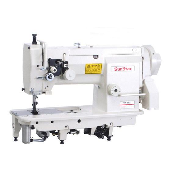
KM-560
One needle, drop feed,
needle feed sewing machine
KM-560-7
One needle, drop feed,
needle feed sewing machine
with automatic thread trimmer
(Equipped with FORTUNA AC
SERVO MOTOR)
1) For proper use of the machine, thoroughly
read this manual before use.
2) Keep this manual in a safe place for future
reference in case the machine breaks down.
M M M M E E - - 0 0 5 5 0 0 6 6 2 2 9 9
Advertisement
Table of Contents

Related Manuals for SunStar KM-560


Summary of Contents for SunStar KM-560
- Page 1 User’s Manual KM-560 One needle, drop feed, needle feed sewing machine KM-560-7 One needle, drop feed, needle feed sewing machine with automatic thread trimmer (Equipped with FORTUNA AC SERVO MOTOR) 1) For proper use of the machine, thoroughly read this manual before use.
- Page 2 1. Thank you for purchasing our product. Based on the rich expertise and experience accumulated in industrial sewing machine production, SUNSTAR will manufacture industrial sewing machines, which deliver more diverse functions, high performance, powerful operation, enhanced durability, and more sophisticated design to meet a number of user’s needs.
-
Page 3: Table Of Contents
Table of contents Safety rules for machine ............................4 1. Specification ................................8 1) Sewing machine ................................. 8 2) Motor ..................................8 3) Peripheral automation device (optional) ........................8 2. Installation ................................9 1) Installation of machine head ............................9 2) Installation of knee lifting solenoid and power switch box (for automatic thread trimming) ......... -
Page 4: Safety Rules For Machine
Safety Rules for Machine Safety labels in the manual are categorized into danger, warning and caution. Failure to follow the safety rules may result in physical injuries or mechanical damages. The safety labels and symbols are defined as follows. [The meaning of the safety labels] Danger Danger Instructions here shall be observed strictly. - Page 5 1-1) Machine Only personnel with a full understanding of the safety rules should move the machines. mobilization The following directions must be observed when delivering the machines. ⓐ At least two persons should work together. ⓑ In case the machine should be transported, please wipe the oil covered on the machine to prevent accidents Danger 1-2) Machine...
- Page 6 1-4) Machine KM-560 series are manufactured for industry use to sew textiles and other similar material. Operation In case of running the machine, users should observe the following things. ⓐ Ahead of operating the machine, please read the manual and understand fully the details on its operation.
- Page 7 1-6) Position of “Caution” is attached to the machine for safety. Caution Mark In case of starting to run the machine, read the directions of “Cautions” carefully. [Position of Caution Mark] CAUTION 경 고 Do not operate without finger guard and safety devices.
-
Page 8: Specification
Specification 1) Sewing machine Item KM-560-7(Trimming type) KM-560(Ordinary type) Usage Heavy materials ∼ Ultra thin materials Max speed 3,000 SPM Max stitch length 8 mm Needle bar stroke 34.2 mm Vertical stroke of upper feed presser foot and auxiliary 2 ∼ 5.5mm... -
Page 9: Installation
Installation Caution ▶ Installation of the machine should be performed by a trained engineer. ▶ Any electrical wiring must be performed by a qualified technician or agent. ▶ The machine weighs over 38 kg. At least 2 persons should carry out the installing work. ▶... -
Page 10: Installation Of Oil Fan
3) Installation of oil fan ※ Insert the projecting part of the oil fan ② into the respective machine holes on the lower side of the table ①, and then push securely to the right. Fix the oil fan to Nail the four fixing spots ③... -
Page 11: Installation Of The Program Unit (For Automatic Trimming Type)
⑷ Attach belt cover “C” ④ to the table. Make sure that the belt properly operates without interference from the belt cover “C” . (See Figure 7) ④ [Figure 7] 6) Installation of the program unit (for automatic trimming type) ⑥... -
Page 12: Assembly Of The Location Detector And Its Control Method (For Automatic Trimming Type)
8) Assembly of the location detector and its control method (for automatic trimming type) ⑴ Installation of the location detector Assemble in the order of marked numbers as can be seen in Figure 10. Then, following Figure 11, make adjustments to place the photo film at the center of the sensor housing ①, by moving the shaft ②... -
Page 13: Oil Supply
Caution ▶ Be sure to plug in after finishing oil supply. ▶ If the user steps on the pedal by mistake, the machine will start automatically, and this might lead to physical injuries. ▶ When handling lubricant, use safety goggle or gloves to prevent the lubricant from coming into contact with the eyes or skin. -
Page 14: Checking Stop Position Of The Sewing Machine (For Automatic Trimming Type)
⑷ Lubrication check at hook After 10-second operation of the machine, check the amount of oil sprayed from the hook looks like the picture in Figure 18. The amount of oil for the hook can The oil be adjusted by using the adjustment screw ① on the sprayed hook base. -
Page 15: Adjustment Of The Machine
Adjustment of the Machine Caution ▶ Always turn off the power when mounting a needle. ▶ If the operator mistakenly steps on the pedal while the power is on, the machine will start automatically and can result in physical injuries. ▶... -
Page 16: Routing The Upper Thread
Caution ▶ Turn off the power switch when routing the upper thread. ▶ If the operator mistakenly steps on the pedal while switched on, the machine will start automatically and can cause physical injuries. ▶ When using the clutch motor, be aware that the motor will continue to rotate for a while after the power is switched off due to inertia. - Page 17 ⑶ Adjusting the tension of thread take up lever spring Adjusting the thread take up stroke As in figure 27, loosen the stopper clamp screw ⑥, and turn the thread take up lever’ s spring stopper ④ clockwise to make the stroke smaller and counter clockwise to make it bigger. ※...
-
Page 18: Adjusting The Tension Of The Presser Foot
Caution ▶ After disassembling and adjusting a safety device, always place it back to the original position and check whether it functions as intended. ▶ Use both hands when pushing the machine backward or returning it to the original position. Due to the weight of the machine, your hand can get stuck in the machine if you should slip. -
Page 19: Adjusting The Position Of The Feed Dog
⑵ As in Figure 33, check whether the needle tip matches ② the upper side of the needle plate at the moment when the upper side of the feed dog ① and the upper side of the needle plate ② match each other. ①... -
Page 20: Adjusting Timing Of Needle And Hook
9) Adjusting timing of needle and hook ⑴ Fixing the height of the needle bar ※ Turn the pulley to make the needle bar be placed in its lowest position. Loosen the needle bar holding screw① in Figure 37 to make sure that the needle bar carved sign ⓐ meets the end ⓑ of the frame, then tighten the screw. ⓑ... -
Page 21: Clearance Adjustment Between The Upper Side Of Hook Stopper And The Upper Side Of Needle Board Groove
⑶ Adjusting the distance between the needle and the hook edge Raise the needle from its lowest point so that the hook edge meets the needle center. As in Figure 40, when the lower part of the needle meets the balance point of the hook’ s needle guide plate ① (adjust the needle guide form), adjust the distance between the hook edge and the inner side of the needle groove to 0.05~0.1 mm. -
Page 22: Adjusting Feed Dog Height
12) Adjusting feed dog height Turn the pulley so that the feed dog ① is positioned at its hight to adjust the feed dog ①. Loosen the fork clamp screw ④ of the feed dog base as in Figure 44 and move the feed dog base up and down so that the feed dog protrudes about 1 mm from the needle plate top. - Page 23 ⑵ Adjusting the height of the strokes of both different ④ 10.5mm ② ⑤ ③ [Figure 46] Adjusting the auxiliary presser foot ※ Loosen the pressure-adjusting screw ④ and the bracket-fastening screw ⑤. ※ Adjust the bracket-fastening screw ⑤ so that the auxiliary presser foot① rise about 10.5 mm from the needle plate top when the pressure lifter ③...
-
Page 24: Adjusting Timing Of The Auxiliary Presser Foot, The Upper Feed Foot And The Needle
14) Adjusting timing of the auxiliary presser foot, the upper feed foot and the needle When the needle ① goes down, the upper feed presser foot ③ should adhere to the feed dog ② before the needle edge adheres to the upper part of the feed dog ②. The upper feed presser foot ③ should continue to adhere to the feed dog ② even when the needle ①... -
Page 25: Adjusting Safety Device
16) Adjusting safety device If the load occurs by foreign substances on thread, needle, etc, during the sewing operation, the driving ball of safety assembly in Figure 49 is removed to prevent damage of the hook and other major parts from the lood, and the pulley ② and the clutch plate ③... - Page 26 ⑦ ⑧ ① Complementary straight line ⑥ ② Trimming finishing point ⑩ ⑨ ④ ① ⑤ Movable knife operation starting point ⑥ [Trimming Cam Lead] (※ The present stop position of the cam: roller is inside the complementary straight line with the cam lead, right before it exits having finished trimming action) [Figure 51] ①...
- Page 27 ① When the whole trimmer shake linkage ① is in up position, that is, when it has come back to its original position after finishing trimming, the distance ④ between the lower part of the roller ② and the equal point of the trimming cam ③...
- Page 28 ⑶ Adjusting movable knife and fixed knife Adjusting the position of movable knife-edge and hook stopper ① ② ③ 0.05~0.2 ⑧ ④ ⑩ ⑥⑤ ⑦ ⑨ ⑧ ⑪ [Figure 54] ① When a movable knife ① passes the front side of the hook stopper ②, adjust the distance ④ to be within 0.05~0.2 mm range like part ③.
- Page 29 Adjusting movable and fixed knife ③ ① As in Figure 55, adjust the position of the fixed knife ③ so that the fixed knife right side edge ② ④ matches the movable knife inner side edge ①. ④ ② The initial assembling position of the movable ⑨...
- Page 30 ※ The standard initial assembling position of the movable knife ① is where the movable knife-edge protrudes about 3mm ③ from the fixed knife edge ② when the trimming action is finished, that is, when the movable knife is in its initial stop position. When fixing the position of the movable knife, the following directions must be followed so that the power generated in the cam ④...
-
Page 31: Replacing Movable Knife And Fixed Knife
18) Replacing movable knife and fixed knife ④ ① ⑤ ⑴ Lift the presser foot ① and open the slide plate ②. ⑨ ⑧ ⑵ Disassemble the needle plate ③. ③ ⑶ Loosen the fixing screw ④, to disassemble the washer ⑥... -
Page 32: Causes Of Troubles And Troubleshooting
Causes of Troubles and Troubleshooting 1) Sewing machine troubleshooting Symptom Checkpoints Root cause Corrective action Direction and height of Needle is inserted into wrong position. Reinsert the needle correctly and push in to needle its highest level. Needle Needle is bent Change the needle. - Page 33 Symptom Checkpoints Root cause Corrective action The gap between the The height and distance between the Readjust the movable knife setting position. movable knife and the movable knife and the hook do not match. hook Check the tension of fixed Tension and contact of movable and fixed Correct the tension adjustment and surface Trimming miss...
-
Page 34: Table Drawing
Table Drawing...
Need help?
Do you have a question about the KM-560 and is the answer not in the manual?
Questions and answers
i have a very old sunstar km 560 korea aprox 30years plus ,i have forgot how to thread the machine and witch way to place the needle