Table of Contents
Advertisement
S S U U N N S S T T A A R R M M A A C C H H I I N N E E R R Y Y C C O O . . , , L L T T D D . .
R
User's
Manual
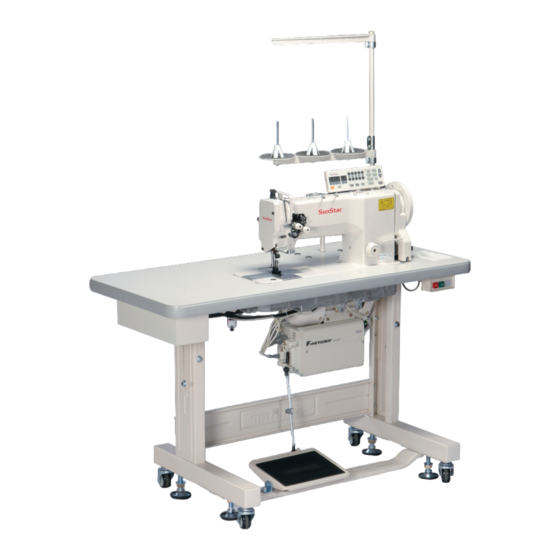
KM-570BL
1 needle, drop feed,
needle feed sewing machine
KM-570BL-7
1 needle, drop feed,
needle feed sewing machine
with automatic thread trimmer
KM-572BL
2 needle, drop feed,
needle feed sewing machine
KM-572BL-7
2 needle, drop feed,
needle feed sewing machine
with automatic thread trimmer
1) For proper use of the machine, thoroughly
read this manual before use.
2) Keep this manual in a safe place for future
reference in case the machine breaks down.
M M M M E E - - 0 0 6 6 0 0 7 7 1 1 0 0
Advertisement
Table of Contents

Related Manuals for SunStar KM-570BL


Summary of Contents for SunStar KM-570BL
- Page 1 User’s Manual KM-570BL 1 needle, drop feed, needle feed sewing machine KM-570BL-7 1 needle, drop feed, needle feed sewing machine with automatic thread trimmer KM-572BL 2 needle, drop feed, needle feed sewing machine KM-572BL-7 2 needle, drop feed, needle feed sewing machine...
- Page 2 1. Thank you for purchasing our product. Based on the rich expertise and experience accumulated in industrial sewing machine production, SUNSTAR will manufacture industrial sewing machines, which deliver more diverse functions, high performance, powerful operation, enhanced durability, and more sophisticated design to meet a number of user’s needs.
-
Page 3: Table Of Contents
Table of contents Safety Rules for Machine ............................4 1. Specification ................................8 1) Sewing machine ................................8 2) Motor ....................................8 3) Peripheral automation devices (optional) ........................8 2. Installation ................................... 9 1) Installation of machine head ............................9 2) Installation of power switch box ........................... -
Page 4: Safety Rules For Machine
Safety Rules for Machine Safety labels in the manual are categorized into danger, warning and caution. Failure to follow the safety rules may result in physical injuries or mechanical damages. The safety labels and symbols are defined as follows. [The meaning of the safety labels] Danger Danger Instructions here shall be observed strictly. - Page 5 1-1) Machine Only personnel with a full understanding of the safety rules should move the machines. mobilization The following directions must be observed when delivering the machines. ⓐ At least two persons should work together. ⓑ In case the machine should be transported, please wipe the oil covered on the machine to prevent accidents Danger Because physical damage such as the functional obstacles and breakdowns are likely to...
- Page 6 KM-570/572 series are manufactured for industry use to sew textiles and other similar 1-4) Machine Operation material. In case of running the machine, users should observe the following things. ⓐ Ahead of operating the machine, please read the manual and understand fully the details on its operation.
- Page 7 1-6) Position of Caution “Caution” is attached to the machine for safety. Mark In case of starting to run the machine, read the directions of “Cautions” carefully. [Position of Caution Mark] CAUTION 경 고 Do not operate without finger guard and safety devices.
-
Page 8: Specification
Specification 1) Sewing machine Category KM-570BL-7 KM-570BL KM-572BL-7 KM-572BL Purpose For Heavy Materials (sheet, bags, tents, sofas, etc.) Lubrication Method Automatic Lubrication Max. Sewing Speed 2,000spm Max. No. of Stitches Needle Stroke 36mm Manual 10.5mm Presser Foot 16mm Lift Automatic 16mm (optional) -... -
Page 9: Installation
Installation Warning ▶ In case of installing the machine, it should be performed by the trained engineer. ▶ In case of wiring work, be sure to leave the work to an expert or an agent. ▶ The machine weight over 42kg. At least 2 persons should carry out the installing work. ▶... -
Page 10: Oil Supply
(2) Filling the oil pan with lubricants A. Fill the lubricant up to the “H” point. B. You should use the exclusive oil provided by “SUNSTAR” for industrial sewing machines or TELLUS C10” of the Shell company. C. If the oil lever drops to the “L” level, replenish it to the “H” point. -
Page 11: Installation Of Program Unit (Trimmer Type)
5) Installation of program unit (Trimmer Type) A. Use 4 fixed screws③ to fix the bracket ② on the program unit① ③ B. In the program unit①, use two fixed bolts ④ to tightly fix the assembled brackets②. ① ② ④... -
Page 12: Installation Of Knee Lifting Pad
8) Installation of knee lifting pad A. Find the lap lifting pad (ass'y) ① in the accessory box and insert it into the shaft of the oil pan's control body ②. B. Loosen bolt ③ and maintain knee-lifting pad in vertical position to tighten it. -
Page 13: Adjustment Of The Machine
Adjustment of the Machine Caution ▶In case of setting the needle, be sure to switch off the power supply. In case the user press on the step by mistake, the machine runs automatically. By doing so, it can cause the physical injuries. ▶In case of using the clutch motor, the motor revolves because of inertia for a while even after switching off the power supply. -
Page 14: Winding The Lower Thread
Caution ▶In case of adjusting the tension of the lower thread, be sure to switch off the power supply. If the users press on the step by mistake, the machine runs automatically. By doing so, it can cause the physical injuries. ▶In case of using the clutch motor, the motor revolves because of inertia for a while even after switching off the power supply. -
Page 15: Adjusting The Thread Tension
5) Adjusting the thread tension Upper thread tension is weak (1) Adjusting the thread tension As in Figure 14, turning clockwise the tension adjustment nut ① of the thread tension control Upper thread tension is strong assembly makes the upper thread tension stronger and counter clockwise makes it weaker. - Page 16 B) Adjusting the thread take up tension As in figure 17, loosen the screw ② of the thread ③ tension control assembly, and insert the driver into Strong the groove of the thread tension control assembly ③. Turn clockwise to make the spring ① tension Weak stronger and counter clockwise to make it weaker.
-
Page 17: Adjusting The Tension Of The Presser Foot
Caution ▶After finishing dismantling or adjusting the safety devices, be sure to install it in the original position properly and check whether it functions as desired or not. ▶In case of bending the machine backward or returning to the original condition, be sure to use both hands. -
Page 18: Clearance Adjustment Between Hook And Opener
(2) Adjusting the timing of hook edge and needle center crossing First, set the stitch length at “0” . Adjust the hook gear clamp screw ① in Figure 25 so that the hook edge fall exactly at the center of the needle center when the needle bar is raised 2.4 mm from its lowest position as in Figure 24. When this is done, the hook edge will be placed at about 1.5 mm above from the front of the needle thread hole. -
Page 19: Adjusting Feed Dog Height
10) Adjusting feed dog height Turn the pulley so that the feed dog ① is positioned at its hight to adjust the feed dog ①. Loosen the fork clamp screw ④ of the feed dog base as in Figure 29 and move the feed dog base up and down so that the feed dog protrudes about 1 mm from the needle plate top. - Page 20 (2) Adjusting the height of the strokes of both different ④ ① 10.5mm ⑥ ② ⑤ ③ [Figure 31] Adjusting the auxiliary presser foot ※ Loosen the pressure-adjusting screw ④ and the bracket-fastening screw ⑤. ※ Adjust the bracket-fastening screw ⑤ so that the auxiliary presser foot① rise about 10.5 mm from the needle plate top when the pressure lifter ③...
-
Page 21: Adjusting Timing Of The Auxiliary Presser Foot, The Upper Feed Foot And The Needle
12) Adjusting timing of the auxiliary presser foot, the upper feed foot and the needle When the needle ① goes down, the upper feed presser foot ③ should adhere to the feed dog ② before the needle edge adheres to the upper part of the feed dog ②. The upper feed presser foot ③ should continue to adhere to the feed dog ② even when the needle ①... -
Page 22: Adjusting Safety Device
14) Adjusting safety device If the load occurs by foreign substances on thread, needle, etc, during the sewing operation, the driving ball ① of safety assembly in Figure 34 is removed to prevent damage of the hook and other major parts from the lood, and the pulley ② and the clutch plate ③... - Page 23 (2) Distance Adjustment Between Moving Blade and Hook Stopper A) Turn the pulley by hand to place the needle bar at the lowest position. B) Press the trimmer driving link① with the needle at the lowest position. Turn the pulley until the moving blade② reaches to the end.
- Page 24 C) Turn the pulley by hand to place the needle bar at the lowest position. D) Press the trimmer driving link⑥ to insert the trimmer cam roller⑦ into the groove of the trimmer cam④. E) Turn the pulley by hand to make the needle ascend 5mm from the lowest position. Then loosen the trimmer cam screw⑧...
-
Page 25: Adjustment Of Thread Release
16) Adjustment of Thread Release (1) Turn the pulley by hand to place the needle bar at the lowest position. (2) Press the trimmer driving link① to insert the trimmer cam roller② into the groove of the trimmer cam③. (3) Turn the pulley by hand to place the thread take-up lever at the highest position. Loosen the tightening screw④ and adjust the thread release collar⑤... - Page 26 (2) Connect the pneumatic unit and the cylinder as in Figure 42 and 43 by using the pneumatic hoses [Figure 43]...
-
Page 27: Causes Of Troubles And Troubleshooting
Causes of Troubles and Troubleshooting 1) Sewing machine troubleshooting Symptom Checkpoints Root cause Corrective action Direction and height of Needle is inserted into wrong position. Reinsert the needle correctly and push in to needle its highest level. Needle Needle is bent Change the needle. - Page 28 Symptom Checkpoints Root cause Corrective action The gap between the The height and distance between the Readjust the movable knife setting position. movable knife and the movable knife and the hook do not match. hook Check the tension of fixed Tension and contact of movable and fixed Correct the tension adjustment and surface Trimming miss...
-
Page 29: Table Drawing
Table Drawing...
Need help?
Do you have a question about the KM-570BL and is the answer not in the manual?
Questions and answers