Table of Contents
Advertisement
S S u u n n S S t t a a r r C C O O . . , , L L T T D D . .
R
USER ' ' S MANUAL
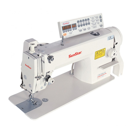
KM-235A/B
High-speed, single-needle
lockstitch sewing machine
with automatic trimming
devices (With FORTUNA AC
SERVO MOTOR)
1) FOR AT MOST USE WITH EASINESS,
PLEASE CERTAINLY READ THIS MANUAL
BEFORE STARTING USE.
2) KEEP THIS MANUAL IN SAFE PLACE
FOR REFERENCE WHEN THE MACHINE
BREAKS DOWN.
M M M M E E - - 0 0 9 9 0 0 9 9 2 2 9 9
Advertisement
Table of Contents

Subscribe to Our Youtube Channel
Related Manuals for SunStar KM-235A


Summary of Contents for SunStar KM-235A
- Page 1 USER ’ ’ S MANUAL KM-235A/B High-speed, single-needle lockstitch sewing machine with automatic trimming devices (With FORTUNA AC SERVO MOTOR) 1) FOR AT MOST USE WITH EASINESS, PLEASE CERTAINLY READ THIS MANUAL BEFORE STARTING USE. 2) KEEP THIS MANUAL IN SAFE PLACE FOR REFERENCE WHEN THE MACHINE BREAKS DOWN.
- Page 2 1. Thank you for purchasing our product. Based on the rich expertise and experience accumulated in industrial sewing machine production, SUNSTAR will manufacture industrial sewing machines, which deliver more diverse functions, high performance, powerful operation, enhanced durability, and more sophisticated design to meet a number of user’s needs.
-
Page 3: Table Of Contents
Contents Safety rules for machines ............................. 4 1. Specifications 1) Sewing machine ................................. 8 2) Controller of Servo Motor ............................8 3) Peripheral automation devices (optional) ........................8 2. Installation 1) Installation of the machine head ..........................9 2) Installation of the knee-lifting solenoid and the power switch box ................. 9 3) Lubrication ................................ -
Page 4: Safety Rules For Machines
Safety rules for machines Safety labels in the manual are categorized into danger, warning and caution. Failure to follow the safety rules may result in physical injuries or mechanical damages. The safety labels and symbols are defined as follows. [The meaning of the safety labels] Danger Instructions here shall be observed strictly. - Page 5 ⓑ No part of the machine or specifications may be modified without prior consultation with our company. Any such modification could risk safe operation of the machine. ⓒ In case of repair, replace only with standard OEM parts from SunStar. ⓓ After repair, put safety covers back on the machine.
- Page 6 1-4) Machine KM-235 Series are intended to be used for industrial purposes for sewing textiles and operation other similar materials. Carefully study the following instructions before operating the machine. ⓐ Read the manual thoroughly and understand the instructions fully before use. ⓑ...
- Page 7 1-6) Location of “Caution”is attached on the machine for safety. Read the directions of “caution” caution mark carefully before running the machine. [Location of caution mark] CAUTION 경 고 Do not operate without finger guard and safety devices. Before threading, changing bobbin and needle, cleaning etc.
-
Page 8: Specifications
SPECIFICATIONS 1) Sewing machine Type KM-235A KM-235B Description Application For light and medium heavy materials For heavy materials Maximum speed 5,500 SPM 4,500 SPM Maximum number of stitch Needle used DB x 1#14 (#9~#18) DB x 1#21 (#20~#25) Thread used... -
Page 9: Installation
INSTALLATION Warning ▶The machine must be installed by a trained technician only. ▶Any electrical wiring must be performed by a qualified technician or agent. ▶The machines weigh over 35 kg. As such, two or more people should carry out the installation. -
Page 10: Lubrication
B. Feeding oil to the oil pan a) Feed the oil to the “HIGH” mark. (Refer to Figure 4) b) Be sure to use the oil for SunStar industrial-use sewing machines or TELLUS C10 from SHELL. c) When the oil is down to LOW level during operation, immediately fill up the oil to HIGH level. -
Page 11: Adjustment Of Belt Tension
4) Adjustment of belt tension After the motor is installed, unfasten fixing nuts ① and ② to give tension to the belt ④ generated by the weight of the motor ③. At this point, fasten the fixing nut ① and fixing nut ②... -
Page 12: Assembly And Adjustment Of The Synchronizer
6) Assembly and adjustment of the synchronizer (1) For in-built location detector Adjust the up-stop position of the needle such that the white carved sign on the pulley ®È is in a straight line with the carved sign on the arm ®Í when the needle has stopped in the air. That adjustment can be made by loosening the pulley’s clamp screw®Á... -
Page 13: Checking Stop Position Of The Sewing Machine
7) Checking stop position of the sewing Needle bar rear bushing machine Press the button ① to operate up/down position of the needle, and check the stop position of the machine. When the needle stops in up-stop position, check if the end surface of the needle bar rear bushing and the carved mark at the lower end of the needle bar come within 0~2mm range. -
Page 14: Adjustment Of The Sewing Machine
ADJUSTMENT OF THE SEWING MACHINE Caution ▶When installing a needle, be sure to turn the power switch off. If the user mistakenly steps on the foothold, the machine will automatically start and can cause injuries. ▶The clutch motor will continue to run for a while due to inertia even after you turn the power switch off. -
Page 15: Adjusting The Oil Supply Of Thread Take-Up Unit
Caution ▶When checking lubrication of the thread take-up unit and the hook, keep your hands or oil check paper away from peripheral feeding devices in order to prevent injuries. 4) Adjusting the oil supply of thread take-up unit As shown in Figure 15, the level of oil supply will increase ④... -
Page 16: Routing Upper Thread
A. Insert the bobbin ② in the bobbin case ①. Insert thread into the thread groove ③ and place it under the tension-adjusting plate spring ④. Turn the tension-adjusting screw ⑤ clockwise to raise the tension of lower thread, and turn it counterclockwise to reduce the tension. -
Page 17: Adjusting Presser Foot Height And Pressure
C. Auxiliary thread adjusting device Turn the auxiliary thread tension-adjusting nut ① clockwise to shorten the thread remaining in the Short needle after trimming. Turn it counterclockwise to lengthen the remaining thread. The appropriate Long length of upper thread that remains in the needle after trimming, is 30~40mm. -
Page 18: Adjusting Stitch Length
10) Adjusting stitch length As illustrated in Figure 23, the number on the stitch- adjusting dial ① shows the stitch length in mm. Turn left and right to get a desired stitch length. (The stitch length will decrease when turned clockwise, and increase when turned counterclockwise.) [ Figure 23 ] Caution... -
Page 19: Adjusting The Feed Cam
12) Adjusting the feed cam As shown in Figure 25, turn the pulley by hand to lower the end of the feed dog ①. When it aligns with the upper side of the needle plate ②, adjust the upper end of the needle hole of the needle ③ to align with the upper side of the needle plate ②. Also at this point, the upper shaft carved line ④... - Page 20 d) After adjustments, operate the trimming cam ① to 0.5mm see if the front side of the assembly gear ② is Trimming drive gear 0.5mm from the front side of the first gear of the “B” trimming cam. (Refer to Figure 28) [ Figure 28 ] e) When the trimming cam ①...
-
Page 21: Tension Adjustment Of The Fixed Blade
D. Position setting of the safety device cam Alignment of carved marks As shown in Figure 32, align the carved mark on the safety device cam ② with the carved mark on the outer part of the trimming cam ①. Firmly tighten two screws ③. -
Page 22: Adjusting The Bobbin Catcher
17) Adjusting the bobbin catcher A. Adjusting the bobbin catcher lever With the bobbin catcher lever ③ not in motion, Bobbin catcher-adjusting line unfasten the lever screw ⑥ to bring the tip of the bobbin catcher lever ③ against the end of the connecting link ②... -
Page 23: Cause Of Troubles And Troubleshooting
CAUSE OF TROUBLES AND TROUBLESHOOTING 1) Sewing machine troubleshooting Symptom Checkpoints Root cause Corrective action Direction and height Needle is inserted into wrong Reinsert the needle correctly of needle position Change the needle Needle is bent Needle Bad timing of feed dog Adjust the timing of feed dog Needle breaks Ascending level of... - Page 24 Symptom Checkpoints Root cause Corrective action Remaining length of upper thread Adjust the thread adjusting device is short Due to bobbin racing during Racing-proof spring trimming, lower thread dropping Change the racing protection Stitch skips of bobbin case from bobbin case becomes too spring short to go up Unable to lift lower thread due to...
-
Page 25: Table Drawing
TABLE DRAWING...
Need help?
Do you have a question about the KM-235A and is the answer not in the manual?
Questions and answers