Table of Contents
Advertisement
S S U U N N S S T T A A R R M M A A C C H H I I N N E E R R Y Y C C O O . . , , L L T T D D . .
R
USER'S
MANUAL
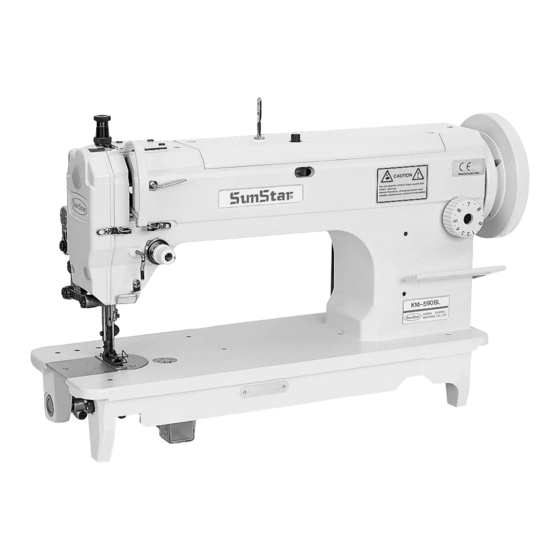
KM-590BL
Single-needle, unison feed
lock stitch sewing machine
(with vertical large hook)
1) For proper and trouble-free use of the
machine, thoroughly read this manual
before use.
2) Keep this manual in a safe place for
future reference in case the machine
breaks down.
M M M M E E - - 0 0 5 5 0 0 5 5 0 0 9 9
Advertisement
Table of Contents

Related Manuals for SunStar KM-590BL


Summary of Contents for SunStar KM-590BL
- Page 1 USER’S MANUAL KM-590BL Single-needle, unison feed lock stitch sewing machine (with vertical large hook) 1) For proper and trouble-free use of the machine, thoroughly read this manual before use. 2) Keep this manual in a safe place for future reference in case the machine breaks down.
- Page 2 1. Thank you for purchasing our product. Based on the rich expertise and experience accumulated in industrial sewing machine production, SUNSTAR will manufacture industrial sewing machines, which deliver more diverse functions, high performance, powerful operation, enhanced durability, and more sophisticated design to meet a number of user’s needs.
-
Page 3: Table Of Contents
Table of contents SAFETY RULES FOR MACHINES ........................4 1. SPECIFICATIONS ..............................8 1) Specifications of KM-590BL ............................ 8 2) Application ................................. 8 2. INSTALLATION ..............................9 1) Installation of the oil fan ............................9 2) Installation of head enclosures ..........................10 3) Lubrication ................................ -
Page 4: Safety Rules For Machines
SAFETY RULES FOR MACHINES Safety labels in the manual are categorized into danger, warning and caution. Failure to follow the safety rules may result in physical injuries or mechanical damages. The safety labels and symbols are defined as follows. [ The meaning of the safety labels ] Danger Instructions here shall be observed strictly. - Page 5 ⓑ No part of the machine or specifications may be modified without prior consultation with Danger our company. Any such modification could risk safe operation of the machine. ⓒ In case of repair, replace only with standard OEM parts from SunStar. ⓓ After repair, put safety covers back on the machine.
- Page 6 KM-590BL series are intended for industrial purposes for sewing textiles and other 1-4) Machine similar materials. Carefully study the following instructions before operating the machine. operation ⓐ Read the manual thoroughly and understand the instructions fully before use. ⓑ Put on proper safety garments.
- Page 7 1-6) Location of Caution mark is attached on the machine for safety. Read the directions of the Caution Caution mark mark carefully before running the machine. [Location of caution mark] CAUTION 경 고 Do not operate without finger guard and safety devices.
-
Page 8: Specifications
SPECIFICATIONS 1) Specifications of KM-590BL DESCRIPTION SPECIFICATION Application For very heavy materials Max. sewing speed 2,000SPM Max. No. of stitches Needle bar stroke 35mm Manual Presser foot height Knee lifting 16mm Needle used DP×17 (#20~#25), standard needle #23 Feed dog height 1~1.2mm... -
Page 9: Installation
INSTALLATION Warning ▶ The machine must be installed by a trained technician only. ▶ Any electrical wiring must be performed by a qualified technician or agent. ▶ The machine weighs over 35 kg. As such, two or more people should carry out the installation. ▶... -
Page 10: Installation Of Head Enclosures
2) Installation of head enclosures ① ③ ② [ Figure 2 ] Insert the head hinge ① into the bed hole and align it well with the head hinge rubber ② of the table. Place the machine on the head support rubber ③. 3) Lubrication Before using the machine, be sure to supply a sufficient amount of oil through the lubrication hole marked with red color. -
Page 11: Adjustment Of Belt Tension
4) Adjustment of belt tension The machine rotates to the left when seen from the pulley. To get a proper level of belt tension, turn the nut ② to an extent at which the belt ① can be bent by 15~20mm when ①... -
Page 12: Adjustment Of The Machine
ADJUSTMENT OF THE MACHINE 1) Placing the needle Insert the needle ① deeply into the hole ② of the needle bar, ② with the long groove of the needle facing left. Then, tighten the ③ screw ③ to hold the needle. ①... -
Page 13: Routing The Upper Thread
4) Routing the upper thread ② ① ③ ⑦ ④ ⑧ ⑨ ⑦ ⑨ ⑤ ⑤ ⑥ ⑥ ⑩ ⑪ ⑫ [ Figure 10 ] Set the thread take-up lever at the highest position. Pass the thread from the left to the right of the needle. Caution ▶... -
Page 14: Adjusting The Spring Tension
6) Adjusting the spring tension ④ Strong 40~60g Large Weak Small ③ [ Figure 12 ] The thread take-up stroke is normally 7~10mm. As a standard, the twisting strength of the thread take-up spring is 40~60 g. Loosen the screw ③ of the thread take-up lever and turn the thread-adjusting device to achieve the proper thread take-up stroke. -
Page 15: Adjusting The Feed Dog Height
9) Adjusting the feed dog height ① ② 1~1.2mm [ Figure 15 ] As a standard, 1~1.2mm is the maximum height of the feed dog when the number of stitches is set at the highest and the feed dog rises above the upper needle plate. Unfasten the screw ①... -
Page 16: Adjusting The Auxiliary Presser Foot And Upper Feed Presser Foot
Caution ▶ Be sure to place back safety devices and check whether they function properly, after disassembling and adjustments. ▶ Use both hands when bending the machine backwards or returning it to the normal position. Using only one hand can lead to physical injuries due to the weight of the machine. ▶... - Page 17 (3) Adjusting Before/After position of the auxiliary presser foot Set the number of stitch at a maximum. Unfasten the screw ② ① ⑨ so that the auxiliary presser foot ① does not touch the ⑩ ⑨ backside of the upper feed presser foot ②. Move to the left and right, the adjusting crank ⑩...
- Page 18 (7) Setting the position of Up/Down movement cam No. 2 screw With the dial set at zero and the needle bar lifter pushed up, manually rotate the pulley to bring the needle bar to its highest position. At this point, place the no. 2 screw of Up/Down movement cam at the 12 o’clock position and Upper No.
- Page 19 MEMO...
- Page 20 MEMO...
- Page 21 MEMO...
- Page 22 MEMO...
- Page 23 MEMO...
Need help?
Do you have a question about the KM-590BL and is the answer not in the manual?
Questions and answers