
Subscribe to Our Youtube Channel
Related Manuals for Extech Instruments DCP60


Summary of Contents for Extech Instruments DCP60
- Page 1 USER GUIDE Model DCP60 and Model DCP60‐220 Switching Mode DC Power Supplies 60V / 10A Adjustable ...
-
Page 2: Introduction And Features
Introduction and Features Thank you for selecting the Extech DCP60 (110V) or DCP60‐220 (220V) Switching Power Supply. The DCP60 is highly efficient, incorporates upgraded SMPS circuitry with small form factor, benefits from an automatic cross‐over for CC and CV, has three (3) Voltage/Current presets, and can be remote controlled. The DCP60 is perfect for solving a variety of loading conditions and applications. Dual action (Course/Fine) tuning provides smooth, accurate, and quick setting of Voltage/Current Setting, changing, and verifying the current limit level is convenient and can be performed without output spiking The Remote Control feature permits output ON/OFF and Voltage/Current adjustments The USB port offers PC connectivity for programming and running ramp cycles with 20 programmable sets of Voltage/Current and varying test durations (up to 999 cycles) Applications and industries where the DCP60 can be employed include laboratory, telecommunications, production testing, field testing, DC network powering, and more Three (3) user programmable Voltage/Current settings offer quick recall of frequently used test settings This device is shipped fully tested and calibrated and, with proper use, will provide years of reliable service. Please visit our website (www.extech.com) to check for the latest version of this User Guide, Product Updates, and Customer Support. DCP60‐EU‐DE v1.4 9/13 ... - Page 3 Safety This manual contains important safety and operation instructions for correct use of the power supply. Read through the manual and pay special attention to the markings and labels of this unit and equipment to be connected. Pay special attention to these two types of notices used in this manual: WARNING : Failure to observe this warning may cause injury to persons and damage to power supply or connected equipment. CAUTION : Failure to observe this warning may result in damage to equipment and improper functioning of the power supply. WARNING Do not use this power supply near water Do not operate or touch this power supply with wet hands Do not open the casing of the power supply when it is connected to ac mains Refer all servicing to qualified service personnel only Before replacing the AC fuse, determine the cause and clear up the cause first Replace the AC fuse with the same type and rating as the original fuse The maximum output voltage of the DCP60 exceeds 60VDC, avoid touching the metal contact parts at the output terminals CAUTION Use a grounded 3 pin AC source This unit is intended for indoor use only Do not operate or place this unit in a humid, dusty location Do not operate this unit in direct sunlight or near any heat source Before plugging into local AC mains, check with the rating label at the back of the unit Do not block any ventilation openings of the unit This unit must be used within the specified rating; regular excessive continuous loading may cause damage to the power supply The gauge size of the input power cable must be at least 0.75mm and the total length of power cable must not exceed 3m DCP60‐EU‐DE v1.4 9/13 ...
-
Page 4: Power Supply Description
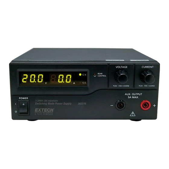
Power Supply Description FRONT PANEL (1) LED panel meter display with CC/CV Indictor (2) Rear Control Indicator (lights when using Preset/ Remote Control/ Set mode) (3) Output Voltage Control Knob (controls both the main and auxiliary output voltage) (4) Output Current Control Knob (controls both the main and auxiliary output current limit) (5) Power ON/OFF Switch (6) Aux. output terminal (max 5A); The total rated current (Aux.+Main) is 10A REAR PANEL (7) Haupt‐Ausgangsklemme (max. 10 A). Der Gesamt‐Nennstrom (Aux+Haupt) beträgt 10 A (8) Mode Selection Switch (Normal, Preset, Remote Control, Set Mode) (9) Abruf‐Wahlschalter – Auswahlschalter der eingestellten Spannung (10) Remote Control Terminal (11) Cooling Fan Air Intake Grille (12) AC Input Plug (13) USB port DCP60‐EU‐DE v1.4 9/13 ... -
Page 5: Normal Mode
Preset Mode In this mode, the Rear Control Light is ON to indicate that the panel V & I controls are de‐ activated. There are three preset outputs P1/ P2/ P3 available using the Recall Selection Switch (9) The preset values are factory set as shown in the table below. The user can change these output settings; please refer to the next paragraph. Recall No. Output Voltage Output Current P1 5V Maximum P2 13.8V Maximum P3 55V Maximum Set Mode Enter the Set Mode by pushing Switch (8) to the Set Mode slot; the power supply is now ready to be preset. To define the preset output P1/ P2/ P3 Move the Recall Switch (9) to position P1, P2 or P3 Adjust the front panel voltage control knob to set the desired voltage value Adjust the front panel current control knob to set the desired current limit value Repeat the procedure for the remaining recall locations P1, P2, P3 if desired. Move Mode Switch (8) from Set to Preset position to confirm the settings. Set Mode Notes: All presets are saved after the power supply has been switched off. Always check the output voltage of the Preset before connecting to a Load. To check the preset values: Move the Mode Switch (8) to the Preset position and then set the Recall Switch (9) to P1, P2 or P3. The V and I settings for the corresponding RECALL P1, P2, P3 memories will be shown on the panel meter. DCP60‐EU‐DE v1.4 9/13 ... -
Page 6: Remote Control Mode
Remote Control Mode To control the output voltage and current by remote control connector (10) please refer to the section entitled Remote Control. Reset to Factory Default settings Switch OFF the power supply Push and hold both front panel voltage and current control knobs at the same time Switch ON the power supply again Release the front panel voltage and current control knobs PC‐Schnittstellensteuerung Beziehen Sie sich zur Steuerung des Netzgeräts über die mitgelieferte Software auf den Abschnitt “PC‐Schnittstellensteuerung”. DCP60‐EU‐DE v1.4 9/13 ... -
Page 7: Operation
Operation Hinweis: Die maximale Ausgangsspannung des DC60 beträgt 60 VDC. Der Summennennstrom beträgt (Aux+Haupt) 10A Powering the Supply Check the rating label of the power supply and ensure that it complies with the AC mains voltage that is to be used. Connect the power supply to the AC Mains using the provided power cord. Ensure that the Mode Switch (8) is set to the Normal Mode position. The Model DCP60 requires a 110VAC power source and the DCP‐220 requires a 220V power source. Switching the Power Supply ON and Self‐Test Information The power supply will perform a series of self‐tests when it is switched on. The LED and other indicators on the front panel will illuminate in sequence. When the cooling fan is being checked, a high speed wind sound can be heard. After the self‐tests, the CV, V and A LED indicators are lit displaying voltage and 0.0 current. To find the CC current level, turn the current control knob one click in either direction. The current display returns to 0.0 after a few seconds. The table below details the self‐test sequence: Self‐test displays Test Software version Segment check C.V. Indicator check C.C. Indicator check Rear control indicator check Return to C.V. Start to check Over voltage protection check Over load protection check ... -
Page 8: Using The Control Knobs
Using the control knobs The rotary encoder control knobs have fine and coarse tuning with ‘clicking’ movement. Push the knobs to toggle between coarse and fine tuning, notice the subtle changes in brightness of the related LED. Adjust the knobs to the desired values by using coarse and then fine tuning. The display will resume its normal brightness after few seconds to confirm an adjustment. Connecting the Power Supply and running a test Connect the equipment under test to the power supply. Red (+) is connected to the positive polarity input of the equipment and Black (‐) is connected to the negative polarity input of the equipment. Switch ON the power supply first; the panel meter & green CV Indicator should illuminate. Next, switch ON the equipment under test; the panel meter & green CV Indicator should remain lit in green. Testing can now begin. When finished, switch OFF the equipment under test first and then switch off the power supply. Einstellen des Netzgeräts im Konstantstrom‐Modus (CC) Stellen Sie den Stromregler auf Minimum Stellen Sie den Spannungsregler auf Maximum Schließen Sie die Ausgangsleitungen miteinander kurz Schalten Sie das Netzgerät ein Drehen Sie den Stromregler auf, bis der gewünschte Stromwert erreicht ist. Schalten Sie das Netzgerät aus Lösen Sie die Ausgangsleitungen voneinander DCP60‐EU‐DE v1.4 9/13 ... -
Page 9: Remote Control Operation
There are two methods for remotely controlling current and voltage adjustments. Current must be controlled for both methods otherwise the unit will default to CC mode. REMOTE CONTROL – METHOD 1: Using two external DC voltage sources Remote Socket Pin Assignment for external variable voltage source PIN FUNCTIONS REMARKS 1 Internal DC +5V Lower than 50mA 2 Voltage adjust 0 to 5V Externes VDC‐Signal 3 Current adjust 0 to 5V Externes VDC‐Signal 4 Ground 5 Output OFF Short to ground 6 N.A. 7 N.A. 8 N.A. Check the output voltage range of the power supply by varying the external voltage source. Short circuit the main output with 10AWG wire to check the CC setting on the display while varying the external voltage source. DCP60‐EU‐DE v1.4 9/13 ... -
Page 10: Remote Control - Method 2: Using Two 0 To 5K Ohm Variable Resistors
REMOTE CONTROL – METHOD 2: Using two 0 to 5K Ohm variable resistors Remote Socket Pin Assignment for external variable resistor PIN FUNCTIONS REMARKS 1 Internal DC +5V One end of resistor 2 Voltage adjust Variable leg of resistor 3 Current adjust Variable leg of resistor 4 Ground Other end of resistor 5 Output OFF/EIN Short to ground zum Ausschalten 6 N.A. 7 N.A. 8 N.A. Check the output voltage range of the power supply by adjusting the 5Kohm variable resistor. Short circuit the main output with 10AWG wire to check the CC setting on the display while adjusting the variable resistor. DCP60‐EU‐DE v1.4 9/13 ... -
Page 11: Remote Control Output On/Off
Remote Control Output ON/OFF Remote output ON/OFF control can be activated in any of the modes Normal, Preset, Set, and Remote. Review the conditions below: By default, when Pin 5 is open and the output is ON. Shorting Pin 5 to Pin 4 (ground) switches the output OFF. When the output is OFF, the C.V. & C.C. LEDs will flash. The present output voltage and current setting will be shown on the panel meter. The user can adjust the output using the voltage & current control knob to the desired value when the output is OFF. Remark: Use only the 8‐pin remote plug provided and connect with 22AWG wires. See diagram below. Note: Pin numbers are marked on the black area of the socket DCP60‐EU‐DE v1.4 9/13 ... -
Page 12: Pc Interface Control
PC Interface Control Quick Start Software Installation Instructions 1. Create a new folder on the desktop of the PC, which is to be loaded with the DCP60 software. Name the folder DCP60 or any easily distinguishable name. 2. Insert the DCP60 PC Interface Software CD into the CD/DVD drive. When the Auto Play dialog box appears, select “Open folder to view files”. 3. Select all files on the CD and copy them into the folder that was created in Step 1. 4. Close the DCP60 software CD file and remove the CD from the CD/DVD drive. 5. Open the desktop folder created in Step 1, then open the USB CP210x Drivers V6.5 for Win_XP_S2K3_Vista_7 subfolder. 6. Double‐click on the executable file CP210xVCPInstaller.exe from within the USB Drivers folder. 7. Ensure your anti‐virus or network security application is set to permit the execution of the installer file. 8. When the Silicon Labs prompt appears, select Install to load the necessary drivers onto your PC. An older version of the drivers may already reside on your PC; therefore, if prompted to update the drivers, select Yes. 9. Once the drivers have been loaded/updated, restart the PC. 10. After the PC has been restarted, open the desktop folder once more. Open the hcs subfolder and launch the hcs.exe executable file. 11. Connect the Power Supply to the PC via the supplied USB cable. Software Overview The supplied PC software offers three main features: External Timed Programs: Automatic Voltage/Current stepping and program cycling Internal Preset Memory: Three pre‐programmed fixed Voltage/Current presets Datalogging: Automatic recording of voltage and current outputs with programmable sample rate Supported Operating Systems: Windows XP/Vista/7 (32bits/64bits) Driver: Silicon Lab CP210x USB driver (Included in CDROM folder “USB CP210x Drivers V6.5 for Win_XP_S2K3_Vista_7”) Executable Program: run “DCP60\hcs\hcs.exe” ... - Page 13 Main Interface Display The Main interface is divided into 7 panels. Display panel: Indicates real‐time power supply information. Main Configuration and Datalogger Display panel: Use this panel to adjust general program settings and to view External Timed Programs, Internal Preset Memory data, and Datalogger information. Voltage and Current setting panel: Use this panel to set the output values and to switch the output On/Off. Data handling panel: Use this panel to save, load and print data. External Timed Program Description field: Enter a customized description for an External Timed Sequence. Program running cycle setting panel: Set the desired number of running cycles for the External Timed Sequence. Information panel: Displays the Maximum voltage/ current, Datalogger Sampling time (rate), upper voltage/ current limits, and software version. DCP60‐EU‐DE v1.4 9/13 ...
-
Page 14: Display Panel
Display Panel Actual Output Voltage, Current, and Power values C.V./ C.C. Mode status Setting values Output ON/OFF status Output Setting Panel Voltage Output setting Current Output setting Output ON/OFF setting SET (confirm) output values Directly type the value in the Voltage and Current fields or use the slider to set the Voltage and Current values and then press SET to confirm. Click ON or OFF to set the output status. Hinweis: Sobald der Schieberegler aktiv ist, können Sie die Pfeiltasten (links und rechts) der Tastatur zur Feineinstellung nutzen. DCP60‐EU‐DE v1.4 9/13 ... - Page 15 Registerkarte „Setting“ (Einstellung) Auf der „Setting“‐Seite können die unten aufgeführten allgemeinen Programmeinstellungen konfiguriert werden: Wählen Sie die gewünschte Sprache. Wählen Sie die Nummer der seriellen Schnittstelle des PCs, an die das Netzgerät angeschlossen werden soll. Stellen Sie mit dem Schieberegler die Datenlogger‐Abtastdauer (Rate) ein. Stellen Sie den oberen Grenzwert der Ausgangsspannung (UVL) ein, um Niederspannungsanwendungen zu schützen. Stellen Sie den oberen Grenzwert des Ausgangsstroms (UCL) ein, um Anwendungen mit niedriger Stromaufnahme zu schützen. Klicken Sie auf die Schaltfläche DEFAULT (Standard), um den Datenlogger auf seine Werkseinstellungen zurückzusetzen. Bestätigen Sie die Einstellungen mit OK. DCP60‐EU‐DE v1.4 9/13 ...
- Page 16 Externes zeitgesteuertes Programm Externe zeitgesteuerte Programme werden vollständig vom PC kontrolliert. Der PC wechselt auf der Grundlage der vorprogrammierten Einstellungen automatisch die Spannungs‐ und Stromausgabewerte (und ihre Dauer). Klicken Sie auf die Registerkarte EXTERNAL TIMED PROGRAM (externes zeitgesteuertes Programm) und doppelklicken Sie dann auf eine Zelle, um einen Wert festzulegen. Zum Beispiel (siehe Abbildung unten) auf die Spannung in Schritt 2 und schieben Sie den Anfasser, bis der gewünschte Ausgangswert erreicht ist. Sobald der Schieberegler aktiv ist, können Sie die Pfeiltasten (links und rechts) der Tastatur zur Feineinstellung nutzen. Stellen Sie die Dauer für diesen Schritt ein, wie in der Abbildung unten dargestellt. Der Zeitbereich beträgt 0 bis 9 Stunden/59 Minuten/59 Sekunden. Klicken Sie auf die Aufwärts‐/Abwärts‐ Pfeilsymbole oder geben Sie den Wert direkt ein. Wenn die Zeit auf „0“ eingestellt wurde, wird der Schritt übersprungen. Stellen Sie den Zyklus (Anzahl, wie oft die gesamte Sequenz ausgeführt wird) wie unten dargestellt ein. Der Bereich liegt zwischen 0 und 999 Zyklen. Verwenden Sie den Schieberegler oder geben Sie die Anzahl der Zyklen direkt in das Feld ein. Stellen Sie den Zykluswert auf Null, um die Sequenz endlos auszuführen. DCP60‐EU‐DE v1.4 9/13 ...
- Page 17 Klicken Sie auf RUN (Ausführen), um den Zyklus zu starten. Klicken Sie auf STOP (Beenden), um den Zyklus zu beenden. Klicken Sie auf CLEAR TABLE (Tabelle löschen), um alle Einstellungen zu löschen. Warnung: Ist die Sequenz abgeschlossen, werden die Ausgangseinstellungen, zusammen mit den Einstellungen der linken Seite dieses Fensters, angezeigt. Vergewissern Sie sich, dass diese Einstellungen angemessen sind, um Schäden an Ihrem Prüfling zu vermeiden. Interner Vorbelegungsspeicher Die Fernsteuerung‐Vorbelegungsfunktion der PC‐Schnittstelle vereinfacht den langwierigen Eingabevorgang von Gruppen von Einträgen. Da alle Daten auf dem PC‐Monitor gleichzeitig dargestellt werden, wird die Eingabe falscher Daten stark verringert. Die Daten verschiedener Gruppen können klassifiziert, gespeichert, exportiert und jeder Zeit abgerufen werden. Darüber hinaus werden die Daten rot angezeigt, wenn sie die eingestellten Spannungs‐/Stromgrenzwerte überschreiten. Klicken Sie auf „Clear Table“ (Tabelle löschen), um alle Daten der angezeigten Tabelle zu löschen, damit neue Daten eingegeben werden können. Klicken Sie auf „Read for PS“ (Vom Netzgerät lesen), um Daten vom Netzgerät einzulesen. DCP60‐EU‐DE v1.4 9/13 ...
- Page 18 Datenloggerfenster Bewegen Sie mit dem Schieberegler die angezeigte Wellenform nach links oder rechts. Stellen Sie mit dem Schieberegler die Vergrößerung und Verkleinerung ein. Hinweis: Sobald der Schieberegler aktiv ist, können Sie die Pfeiltasten (links und rechts) der Tastatur zur Feineinstellung nutzen. Das grafische Datenloggerfenster zeigt den zeitlichen Verlauf von Spannung, Strom und Leistung am Ausgang an. DCP60‐EU‐DE v1.4 9/13 ...
- Page 19 Save, Load, and Print Data External Timed Program tab The buttons are used to Save and Load an External Timed Program or Print the current settings. If desired, add a description in the Program Description field. Click to save an External Timed Program to a CSV file. Click to open and load settings from a CSV file. Click to print the settings. Internal Preset Memory tab The buttons are used to Save and Load Internal Preset data or Print the current settings. If desired, add a description in the Program Description field. Click to save an Internal Preset Memory set to a CSV file. Click to open and load a setting from CSV file. Click to print a setting. Datalog tab The buttons are used to Save and Load a Datalog file or Print the current settings. If desired, add a description in the Program Description field. Save the data in CSV format for later analysis. Open and load data from CSV document. Print the data. DCP60‐EU‐DE v1.4 9/13 ...
- Page 20 Meaning: The PS Display value is 15V and 16A. It is in CC mode. Input Command: Get preset upper limit of output Voltage Input command: GOVP[CR] <voltage>=??? GOVP[CR] Return value: Return value: <voltage>[CR] 111[CR] OK[CR] OK[CR] Meaning: The preset upper limit of output Voltage is 11.1V Input Command: Preset upper limit of output Voltage Input command: SOVP<voltage>[CR] <voltage>=000<???<Max‐Volt SOVP151[CR] Return value: *Max‐Volt value refer to product Return value: OK[CR] specification OK[CR] Meaning: Preset upper limit of output Voltage as 15.1V DCP60‐EU‐DE v1.4 9/13 ...
- Page 21 GETM[CR] Return value: <voltageX>=??? Return value: <voltage0><current0>[CR] <currentX>=??? 111111[CR] <voltage1><current1>[CR] (X is memory location number start from 0 122122[CR] <voltage2><current2>[CR] to 2) 133133[CR] OK[CR] OK[CR] Meaning: PS return following preset value from memory locations; Memory 0 is 11.1V and 11.1A Memory 1 is 12.2V and 12.2A Memory 2 is 13.3V and 13.3A Input Command: Set Voltage and Current using values saved Input command: RUNM<memory>[CR] in memory locations RUNM1[CR] Return value: <memory>=0/1/2 Return value: OK[CR] OK[CR] Meaning: Set Voltage and Current using values saved in memory location 1 DCP60‐EU‐DE v1.4 9/13 ...
-
Page 22: Specifications
Specifications Output Variable Voltage Output 1 to 60VDC Variable Current Output 0 to 10ADC Voltage Regulation Load (10 to 100% Load) 50mV Model DCP60 Line (90 to 130VAC Variation): 20mV Model DCP60‐220 Line (170 to 264VAC Variation): 20mV Current Regulation Load (10 to 90% rated voltage) 100mA Model DCP60 Line (90 to 130VAC Variation): 50mA Model DCP60‐220 Line (170 to 264VAC Variation: 50mA Ripple and Noise Ripple and Noise (RMS) voltage 5mV Ripple and Noise (P‐P) voltage 100mv Current Ripple and Noise (RMS) 10mA Input Input Voltage Model DCP60: ... -
Page 23: Troubleshooting
Troubleshooting OUP: Over Voltage Protection This unit has a built‐in tracking over voltage protection feature. In the event of output voltage becoming greater than the set value (see specified range from specifications table), protection will be triggered and the output power will be cut off and OUP warning appears as below. To reset the warning, switch off the unit and remove all loading. Switch the unit back on again and it should resume normal operation. If this problem persists, please contact the customer care department or the point of purchase. OTP: Over Temperature Protection There is a thermo sensor inside the unit to monitor and prevent the unit from unduly heating internally. When an OTP error occurs, there is no output and the following warning will appear on the LED display. When this warning appears, switch off the unit and remove all loading. Check the load and output setting. Allow the unit to cool for at least 30 minutes. Check to see if any ventilation holes are blocked, also check that there is sufficient clearance around the power supply. Listen carefully for the short wind sound emanating from the cooling fan when the unit is switched ON again. If the wind sound is not detected, the fan may be faulty; do not use the power supply in this case, contact the customer care department or the agent from the point of purchase. OLP: Over Load Protection Normally the overload protection is sustained by the CC constant current mode. When the CC mode fails and goes undetected, serious damage to the test piece or load may occur. The OLP is used to minimize the extent of damage to the loads in the event of power supply failure. Switch off the power supply as soon as this warning is seen (as shown below). To reset this warning, switch off the unit and remove all loading. Switch the unit back on again and double check with caution. If this problem persists, please contact the customer care department or and consult with the agent at the point of purchase. DCP60‐EU‐DE v1.4 9/13 ... -
Page 24: Warranty
Warranty FLIR Systems, Inc. warrants this Extech Instruments brand device to be free of defects in parts and workmanship for one year from date of shipment (a six month limited warranty applies to sensors and cables). If it should become necessary to return the instrument for service during or beyond the warranty period, contact the Customer Service Department for authorization. Visit the website www.extech.com for contact information. A Return Authorization (RA) number must be issued before any product is returned. The sender is responsible for shipping charges, freight, insurance and proper packaging to prevent damage in transit. This warranty does not apply to defects resulting from action of the user such as misuse, improper wiring, operation outside of specification, improper maintenance or repair, or unauthorized modification. FLIR Systems, Inc. specifically disclaims any implied warranties or merchantability or fitness for a specific purpose and will not be liable for any direct, indirect, incidental or consequential damages. FLIR’s total liability is limited to repair or replacement of the product. The warranty set forth above is inclusive and no other warranty, whether written or oral, is expressed or implied. Calibration, Repair, and Customer Care Services FLIR Systems, Inc. offers repair and calibration services for the Extech Instruments products we sell. NIST certification for most products is also provided. Call the Customer Service Department for information on calibration services available for this product. Annual calibrations should be performed to verify meter performance and accuracy. Technical support and general customer service is also provided, refer to the contact information provided below. Support Lines: U.S. (877) 439‐8324; International: +1 (603) 324‐7800 Technical Support: Option 3; E‐mail: support@extech.com Repair & Returns: Option 4; E‐mail: repair@extech.com Product specifications are subject to change without notice Please visit our website for the most up‐to‐date information www.extech.com FLIR Commercial Systems, Inc., 9 Townsend West, Nashua, NH 03063 USA ISO 9001 Certified Copyright © 2013 FLIR Systems, Inc. All rights reserved including the right of reproduction in whole or in part in any form www.extech.com DCP60‐EU‐DE v1.4 9/13 ... -
Page 25: Garantie
Garantie FLIR Systems, Inc. garantit que cet appareil Extech Instruments est exempt de défauts matériaux et de fabrication pendant un an à partir de la date d’envoi (une garantie limitée de six mois s’applique aux capteurs et aux câbles). Si le renvoi de l’appareil pour réparation devient nécessaire durant ou après la période de garantie, contactez le service client pour autorisation. Pour obtenir les coordonnées, visitez le site Web suivant : www.extech.com. Un numéro d’autorisation de retour (AR) doit être délivré avant tout retour de produit. L’expéditeur prend à sa charge les frais d’expédition, le fret, l’assurance et l’emballage correct de l’appareil afin de prévenir toute détérioration durant le transport. Cette garantie ne s’applique pas aux dommages imputables à l’utilisateur, tels que l’usage impropre ou abusif, un mauvais câblage, une utilisation non conforme aux spécifications, un entretien ou une réparation incorrecte, ou toute modification non autorisée. FLIR Systems, Inc. déclinera spécifiquement toute garantie ou qualité marchande ou aptitude à l’emploi prévu, et ne sera en aucun cas tenu responsable pour tout dommage conséquent, direct, indirect ou accidentel. La responsabilité totale de FLIR est limitée à la réparation ou au remplacement du produit. La garantie définie ci‐dessus est inclusive et aucune autre garantie, écrite ou orale, n’est exprimée ou implicite. Calibrage, réparation et services après‐vente FLIR Systems, Inc. offre des services de calibrage et de réparation pour les produits Extech Instruments que nous commercialisons. Nous fournissons également une certification NIST pour la plupart des produits. Contactez notre service client pour toute information sur les services de calibrage disponibles pour ce produit. Un calibrage doit être effectué chaque année pour vérifier les performances et la précision du mètre. Nous offrons également une assistance technique et un service à la clientèle. Veuillez vous reporter aux coordonnées fournies ci‐dessous. Lignes d’assistance: États‐Unis (877) 439‐8324; international: +1 (603) 324‐7800 Service d’assistance technique : Option 3 ; E‐mail : support@extech.com Réparations et retours : Option 4 ; E‐mail : repair@extech.com Les spécifications produit sont sujettes à modifications sans préavis. Pour les toutes dernières informations, veuillez visiter notre site Web. www.extech.com FLIR Commercial Systems, Inc., 9 Townsend West, Nashua, NH 03063 USA Certifié ISO 9001 Copyright © 2013 FLIR Systems, Inc. Tous droits réservés, y compris la reproduction partielle ou totale sous quelque forme que ce soit. www.extech.com DCP60‐EU‐DE v1.4 9/13 ... - Page 26 Garantía FLIR Systems, Inc., garantiza este dispositivo marca Extech Instruments para estar libre de defectos en partes o mano de obra durante un año a partir de la fecha de embarque (se aplica una garantía limitada de seis meses para cables y sensores). Si fuera necesario regresar el instrumento para servicio durante o después del periodo de garantía, llame al Departamento de Servicio a Clientes para obtener autorización. Visite www.extech.com para Información de contacto. Se debe expedir un número de Autorización de Devolución (AD) antes de regresar cualquier producto. El remitente es responsable de los gastos de embarque, flete, seguro y empaque apropiado para prevenir daños en tránsito. Esta garantía no se aplica a defectos resultantes de las acciones del usuario como el mal uso, alambrado equivocado, operación fuera de las especificaciones, mantenimiento o reparación inadecuada o modificación no autorizada. FLIR Systems, Inc., rechaza específicamente cualesquier garantías implícitas o factibilidad de comercialización o idoneidad para cualquier propósito determinado y no será responsable por cualesquier daños directos, indirectos, incidentales o consecuentes. La responsabilidad total de FLIR está limitada a la reparación o reemplazo del producto. La garantía precedente es inclusiva y no hay otra garantía ya sea escrita u oral, expresa o implícita. Servicios de calibración, reparación y atención a clientes FLIR Systems, Inc., ofrece servicios de reparación y calibración para los productos que vendemos de Extech Instruments. Además ofrecemos certificación NIST para la mayoría de los productos. Llame al Departamento de Servicio al Cliente para solicitar información de calibración para este producto. Para verificar el funcionamiento y precisión se debe realizar la calibración anual. Además se provee Soporte Técnico y servicios generales al cliente, consulte la información de contacto en seguida. Líneas de soporte: EE.UU. (877) 439‐8324; Internacional: +1 (603) 324‐7800 Soporte Técnico Opción 3; correo electrónico: support@extech.com Reparación / Devoluciones: Opción 4; correo electrónico: repair@extech.com Las especificaciones del producto están sujetas a cambios sin aviso Por favor visite nuestra página en Internet para la información más actualizada www.extech.com FLIR Commercial Systems, Inc., 9 Townsend West, Nashua, NH 03063 USA Certificado ISO 9001 Copyright © 2013 FLIR Systems, Inc. Reservados todos los derechos, incluyendo el derecho de reproducción total o parcial en cualquier medio www.extech.com DCP60‐EU‐DE v1.4 9/13 ...
Need help?
Do you have a question about the DCP60 and is the answer not in the manual?
Questions and answers