Table of Contents
Advertisement
Quick Links
Download this manual
See also:
User Manual
Advertisement
Table of Contents

Subscribe to Our Youtube Channel
Related Manuals for Extech Instruments DCP60


Summary of Contents for Extech Instruments DCP60
- Page 1 USER GUIDE Model DCP60 and Model DCP60‐220 Switching Mode DC Power Supplies 60V / 10A Adjustable ...
-
Page 2: Introduction And Features
Introduction and Features Thank you for selecting the Extech DCP60 (110V) or DCP60‐220 (220V) Switching Power Supply. The DCP60 is highly efficient, incorporates upgraded SMPS circuitry with small form factor, benefits from an automatic cross‐over for CC and CV, has three (3) Voltage/Current presets, and can be remote controlled. The DCP60 is perfect for solving a variety of loading conditions and applications. Dual action (Course/Fine) tuning provides smooth, accurate, and quick setting of Voltage/Current Setting, changing, and verifying the current limit level is convenient and can be performed without output spiking The Remote Control feature permits output ON/OFF and Voltage/Current adjustments The USB port offers PC connectivity for programming and running ramp cycles with 20 programmable sets of Voltage/Current and varying test durations (up to 999 cycles) Applications and industries where the DCP60 can be employed include laboratory, telecommunications, production testing, field testing, DC network powering, and more Three (3) user programmable Voltage/Current settings offer quick recall of frequently used test settings This device is shipped fully tested and calibrated and, with proper use, will provide years of reliable service. Please visit our website (www.extech.com) to check for the latest version of this User Guide, Product Updates, and Customer Support. DCP60‐EU‐IT v1.4 9/13 ... - Page 3 Safety This manual contains important safety and operation instructions for correct use of the power supply. Read through the manual and pay special attention to the markings and labels of this unit and equipment to be connected. Pay special attention to these two types of notices used in this manual: WARNING : Failure to observe this warning may cause injury to persons and damage to power supply or connected equipment. CAUTION : Failure to observe this warning may result in damage to equipment and improper functioning of the power supply. WARNING Do not use this power supply near water Do not operate or touch this power supply with wet hands Do not open the casing of the power supply when it is connected to ac mains Refer all servicing to qualified service personnel only Before replacing the AC fuse, determine the cause and clear up the cause first Replace the AC fuse with the same type and rating as the original fuse The maximum output voltage of the DCP60 exceeds 60VDC, avoid touching the metal contact parts at the output terminals CAUTION Use a grounded 3 pin AC source This unit is intended for indoor use only Do not operate or place this unit in a humid, dusty location Do not operate this unit in direct sunlight or near any heat source Before plugging into local AC mains, check with the rating label at the back of the unit Do not block any ventilation openings of the unit This unit must be used within the specified rating; regular excessive continuous loading may cause damage to the power supply The gauge size of the input power cable must be at least 0.75mm and the total length of power cable must not exceed 3m DCP60‐EU‐IT v1.4 9/13 ...
-
Page 4: Power Supply Description
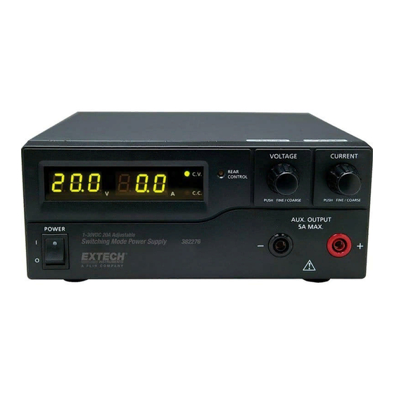
Power Supply Description FRONT PANEL (1) LED panel meter display with CC/CV Indictor (2) Rear Control Indicator (lights when using Preset/ Remote Control/ Set mode) (3) Output Voltage Control Knob (controls both the main and auxiliary output voltage) (4) Output Current Control Knob (controls both the main and auxiliary output current limit) (5) Power ON/OFF Switch (6) Aux. output terminal (max 5A); The total rated current (Aux.+Main) is 10A REAR PANEL (7) Principale terminale d’uscita (nominale per 10A); la corrente nominale totale (Aux. + principale) è 10A (8) Mode Selection Switch (Normal, Preset, Remote Control, Set Mode) (9) Richiama – interruttore di selezione tensione preimpostata (10) Remote Control Terminal (11) Cooling Fan Air Intake Grille (12) AC Input Plug (13) USB port DCP60‐EU‐IT v1.4 9/13 ... -
Page 5: Normal Mode
Preset Mode In this mode, the Rear Control Light is ON to indicate that the panel V & I controls are de‐ activated. There are three preset outputs P1/ P2/ P3 available using the Recall Selection Switch (9) The preset values are factory set as shown in the table below. The user can change these output settings; please refer to the next paragraph. Recall No. Output Voltage Output Current P1 5V Maximum P2 13.8V Maximum P3 55V Maximum Set Mode Enter the Set Mode by pushing Switch (8) to the Set Mode slot; the power supply is now ready to be preset. To define the preset output P1/ P2/ P3 Move the Recall Switch (9) to position P1, P2 or P3 Adjust the front panel voltage control knob to set the desired voltage value Adjust the front panel current control knob to set the desired current limit value Repeat the procedure for the remaining recall locations P1, P2, P3 if desired. Move Mode Switch (8) from Set to Preset position to confirm the settings. Set Mode Notes: All presets are saved after the power supply has been switched off. Always check the output voltage of the Preset before connecting to a Load. To check the preset values: Move the Mode Switch (8) to the Preset position and then set the Recall Switch (9) to P1, P2 or P3. The V and I settings for the corresponding RECALL P1, P2, P3 memories will be shown on the panel meter. DCP60‐EU‐IT v1.4 9/13 ... -
Page 6: Remote Control Mode
Remote Control Mode To control the output voltage and current by remote control connector (10) please refer to the section entitled Remote Control. Reset to Factory Default settings Switch OFF the power supply Push and hold both front panel voltage and current control knobs at the same time Switch ON the power supply again Release the front panel voltage and current control knobs Controllo interfaccia PC Per controllare l’alimentazione tramite il software in dotazione, fare riferimento alla sezione Controllo dell’interfaccia PC. DCP60‐EU‐IT v1.4 9/13 ... -
Page 7: Operation
Operation Nota: La tensione massima in uscita del DC60 è 60VDC e la corrente nominale totale (Aux. + principale) è 10A Powering the Supply Check the rating label of the power supply and ensure that it complies with the AC mains voltage that is to be used. Connect the power supply to the AC Mains using the provided power cord. Ensure that the Mode Switch (8) is set to the Normal Mode position. The Model DCP60 requires a 110VAC power source and the DCP‐220 requires a 220V power source. Switching the Power Supply ON and Self‐Test Information The power supply will perform a series of self‐tests when it is switched on. The LED and other indicators on the front panel will illuminate in sequence. When the cooling fan is being checked, a high speed wind sound can be heard. After the self‐tests, the CV, V and A LED indicators are lit displaying voltage and 0.0 current. To find the CC current level, turn the current control knob one click in either direction. The current display returns to 0.0 after a few seconds. The table below details the self‐test sequence: Self‐test displays Test Software version Segment check C.V. Indicator check C.C. Indicator check Rear control indicator check Return to C.V. Start to check Over voltage protection check Over load protection check ... -
Page 8: Using The Control Knobs
Using the control knobs The rotary encoder control knobs have fine and coarse tuning with ‘clicking’ movement. Push the knobs to toggle between coarse and fine tuning, notice the subtle changes in brightness of the related LED. Adjust the knobs to the desired values by using coarse and then fine tuning. The display will resume its normal brightness after few seconds to confirm an adjustment. Connecting the Power Supply and running a test Connect the equipment under test to the power supply. Red (+) is connected to the positive polarity input of the equipment and Black (‐) is connected to the negative polarity input of the equipment. Switch ON the power supply first; the panel meter & green CV Indicator should illuminate. Next, switch ON the equipment under test; the panel meter & green CV Indicator should remain lit in green. Testing can now begin. When finished, switch OFF the equipment under test first and then switch off the power supply. Impostare l’alimentazione in modalità corrente costante (CC) Girare la manopola della corrente sul minimo Girare la manopola della tensione sul massimo Cortocircuitare tra loro i connettori in uscita Accendere l’alimentatore Girare la manopola della corrente aumentandola fino a raggiungere il valore desiderato. Spegnere l’alimentatore Eliminare il cortocircuito tra i connettori DCP60‐EU‐IT v1.4 9/13 ... -
Page 9: Remote Control Operation
Check the output voltage range of the power supply by varying the external voltage source. Short circuit the main output with 10AWG wire to check the CC setting on the display while varying the external voltage source. REMOTE CONTROL – METHOD 2: Using two 0 to 5K Ohm variable resistors Remote Socket Pin Assignment for external variable resistor PIN FUNCTIONS REMARKS 1 Internal DC +5V One end of resistor 2 Voltage adjust Variable leg of resistor 3 Current adjust Variable leg of resistor 4 Ground Other end of resistor 5 Output OFF/ON Short to ground per Off 6 N.A. 7 N.A. 8 N.A. Check the output voltage range of the power supply by adjusting the 5Kohm variable resistor. Short circuit the main output with 10AWG wire to check the CC setting on the display while adjusting the variable resistor. DCP60‐EU‐IT v1.4 9/13 ... -
Page 10: Remote Control Output On/Off
Remote Control Output ON/OFF Remote output ON/OFF control can be activated in any of the modes Normal, Preset, Set, and Remote. Review the conditions below: By default, when Pin 5 is open and the output is ON. Shorting Pin 5 to Pin 4 (ground) switches the output OFF. When the output is OFF, the C.V. & C.C. LEDs will flash. The present output voltage and current setting will be shown on the panel meter. The user can adjust the output using the voltage & current control knob to the desired value when the output is OFF. Remark: Use only the 8‐pin remote plug provided and connect with 22AWG wires. See diagram below. Note: Pin numbers are marked on the black area of the socket DCP60‐EU‐IT v1.4 9/13 ... -
Page 11: Pc Interface Control
PC Interface Control Quick Start Software Installation Instructions 1. Create a new folder on the desktop of the PC, which is to be loaded with the DCP60 software. Name the folder DCP60 or any easily distinguishable name. 2. Insert the DCP60 PC Interface Software CD into the CD/DVD drive. When the Auto Play dialog box appears, select “Open folder to view files”. 3. Select all files on the CD and copy them into the folder that was created in Step 1. 4. Close the DCP60 software CD file and remove the CD from the CD/DVD drive. 5. Open the desktop folder created in Step 1, then open the USB CP210x Drivers V6.5 for Win_XP_S2K3_Vista_7 subfolder. 6. Double‐click on the executable file CP210xVCPInstaller.exe from within the USB Drivers folder. 7. Ensure your anti‐virus or network security application is set to permit the execution of the installer file. 8. When the Silicon Labs prompt appears, select Install to load the necessary drivers onto your PC. An older version of the drivers may already reside on your PC; therefore, if prompted to update the drivers, select Yes. 9. Once the drivers have been loaded/updated, restart the PC. 10. After the PC has been restarted, open the desktop folder once more. Open the hcs subfolder and launch the hcs.exe executable file. 11. Connect the Power Supply to the PC via the supplied USB cable. Software Overview The supplied PC software offers three main features: External Timed Programs: Automatic Voltage/Current stepping and program cycling Internal Preset Memory: Three pre‐programmed fixed Voltage/Current presets Datalogging: Automatic recording of voltage and current outputs with programmable sample rate Supported Operating Systems: Windows XP/Vista/7 (32bits/64bits) Driver: Silicon Lab CP210x USB driver (Included in CDROM folder “USB CP210x Drivers V6.5 for Win_XP_S2K3_Vista_7”) Executable Program: run “DCP60\hcs\hcs.exe” ... - Page 12 Main Interface Display The Main interface is divided into 7 panels. Display panel: Indicates real‐time power supply information. Main Configuration and Datalogger Display panel: Use this panel to adjust general program settings and to view External Timed Programs, Internal Preset Memory data, and Datalogger information. Voltage and Current setting panel: Use this panel to set the output values and to switch the output On/Off. Data handling panel: Use this panel to save, load and print data. External Timed Program Description field: Enter a customized description for an External Timed Sequence. Program running cycle setting panel: Set the desired number of running cycles for the External Timed Sequence. Information panel: Displays the Maximum voltage/ current, Datalogger Sampling time (rate), upper voltage/ current limits, and software version. DCP60‐EU‐IT v1.4 9/13 ...
-
Page 13: Display Panel
Actual Output Voltage, Current, and Power values C.V./ C.C. Mode status Setting values Output ON/OFF status Output Setting Panel Voltage Output setting Current Output setting Output ON/OFF setting SET (confirm) output values Directly type the value in the Voltage and Current fields or use the slider to set the Voltage and Current values and then press SET to confirm. Click ON or OFF to set the output status. Nota: Quando il cursore è attivo è possibile utilizzare le frecce direzionali destra e sinistra della tastiera per regolare precisamente le impostazioni. Scheda ‘Setting’ Sulla pagina ‘Setting’, impostazioni generali del programma possono essere configurate come elencato di seguito: Selezionare la lingua desiderata Selezionare il numero della Porta PC COM sulla quale sta per essere collegato l'alimentatore Impostare l'intervallo di campionamento del registratore dati (frequenza) usando la barra di scorrimento Impostare il valore del limite superiore della tensione in uscita (UVL) per salvaguardare ulteriormente le applicazioni a bassa tensione DCP60‐EU‐IT v1.4 9/13 ... - Page 14 Impostare il valore del limite superiore di corrente in uscita (UCL) per salvaguardare ulteriormente le applicazioni a bassa corrente Cliccare sul pulsante DEFAULT per rimettere le impostazioni ai valori di fabbrica. Premere OK per confermare le impostazioni. Programma Esterno Temporizzato I Programmi Esterni Temporizzati sono completamente controllati dal PC. Il PC modifica automaticamente le uscite di Tensione e Corrente (e la loro durata temporale) in base alle impostazioni pre‐programmate. DCP60‐EU‐IT v1.4 9/13 ...
- Page 15 Cliccare sulla scheda EXTERNAL TIMED PROGRAM e poi cliccare due volte su una cella per impostare un valore. Per esempio (vedere il disegno di seguito), Passo 2 Tensione, scorrere la barra per impostare il livello d'uscita desiderato Quando il cursore è attivo è possibile utilizzare le frecce direzionali destra e sinistra della tastiera per regolare precisamente le impostazioni. Impostare la durata per questo passo come mostrato nel disegno in basso. Il range di tempo va da 0 a 9 ore/59 minuti/59 secondi. Cliccare sui pulsanti freccia su/giù o digitare il valore direttamente. Se il tempo è impostato su ‘0’ il passo sarà saltato. Impostare il ciclo di lavoro (numero di volte in cui sarà avviata l'intera sequenza) come mostrato di seguito. Range disponibile da 0 a 999 cicli. Usare il cursore o digitare direttamente nel campo per impostare il numero di cicli. Impostare il valore del ciclo su zero per mandare in ciclo la sequenza indefinitamente. Cliccare sul pulsante RUN per avviare il ciclo. Cliccare sul pulsante STOP per arrestare il ciclo. Cliccare sul pulsante CLEAR TABLE per cancellare le impostazioni. Avvertenza: Quando la sequenza è completa, le impostazioni in uscita torneranno a quelle visualizzate nella parte sinistra di questa finestra. Verificare che le impostazioni siano corrette per evitare danni all’UUT. Memoria Preimpostata Interna La capacità di preimpostazione dell'interfaccia remota del PC semplifica il noioso processo di digitazione in gruppi di voci. Dal momento in cui tutti i dati sono visualizzati contemporaneamente sul monitor del PC, la possibilità d'inserire dati in modo scorretto è molto ridotta. Dati di gruppi differenti possono essere classificati, memorizzati, esportati e recuperati per l'uso in qualsiasi momento. Inoltre, i dati recuperati appariranno di colore rosso se superano i limiti preimpostati di tensione/corrente. Cliccare su ‘Clear Table’ per cancellare tutti i dati sulla Tabella del Display per preparare per nuovi dati. Cliccare su ‘Read for PS’ per recuperare dati dall'Alimentatore. DCP60‐EU‐IT v1.4 9/13 ...
- Page 16 Finestra Registratore Dati DCP60‐EU‐IT v1.4 9/13 ...
- Page 17 Regolare il cursore per muovere la forma d'onda visualizzata a sinistra e a destra Regolare il cursore per zoom in (ingrandimento) e zoom out (grandangolo ‐ rimpicciolimento) Nota: Quando il cursore è attivo è possibile utilizzare le frecce direzionali destra e sinistra della tastiera per regolare precisamente le impostazioni. La finestra grafica del registratore dati è utilizzata per visualizzare l'uscita di Tensione, Corrente e Potenza nel tempo. Save, Load, and Print Data External Timed Program tab The buttons are used to Save and Load an External Timed Program or Print the current settings. If desired, add a description in the Program Description field. Click to save an External Timed Program to a CSV file. Click to open and load settings from a CSV file. Click to print the settings. Internal Preset Memory tab The buttons are used to Save and Load Internal Preset data or Print the current settings. If desired, add a description in the Program Description field. Click to save an Internal Preset Memory set to a CSV file. Click to open and load a setting from CSV file. Click to print a setting. Datalog tab The buttons are used to Save and Load a Datalog file or Print the current settings. If desired, add a description in the Program Description field. Save the data in CSV format for later analysis. Open and load data from CSV document. Print the data. DCP60‐EU‐IT v1.4 9/13 ...
- Page 18 Meaning: The PS Display value is 15V and 16A. It is in CC mode. Input Command: Get preset upper limit of output Voltage Input command: GOVP[CR] <voltage>=??? GOVP[CR] Return value: Return value: <voltage>[CR] 111[CR] OK[CR] OK[CR] Meaning: The preset upper limit of output Voltage is 11.1V Input Command: Preset upper limit of output Voltage Input command: SOVP<voltage>[CR] <voltage>=000<???<Max‐Volt SOVP151[CR] Return value: *Max‐Volt value refer to product Return value: OK[CR] specification OK[CR] Meaning: Preset upper limit of output Voltage as 15.1V DCP60‐EU‐IT v1.4 9/13 ...
-
Page 19: Specifications
Memory 0 is 11.1V and 11.1A Memory 1 is 12.2V and 12.2A Memory 2 is 13.3V and 13.3A Input Command: Set Voltage and Current using values saved Input command: RUNM<memory>[CR] in memory locations RUNM1[CR] Return value: <memory>=0/1/2 Return value: OK[CR] OK[CR] Meaning: Set Voltage and Current using values saved in memory location 1 Specifications Output Variable Voltage Output 1 to 60VDC Variable Current Output 0 to 10ADC Voltage Regulation Load (10 to 100% Load) 50mV Model DCP60 Line (90 to 130VAC Variation): 20mV Model DCP60‐220 Line (170 to 264VAC Variation): 20mV DCP60‐EU‐IT v1.4 9/13 ... -
Page 20: Troubleshooting
Current Regulation Load (10 to 90% rated voltage) 100mA Model DCP60 Line (90 to 130VAC Variation): 50mA Model DCP60‐220 Line (170 to 264VAC Variation: 50mA Ripple and Noise Ripple and Noise (RMS) voltage 5mV Ripple and Noise (P‐P) voltage 100mv Current Ripple and Noise (RMS) 10mA Input Input Voltage Model DCP60: 90 to 130VAC 50/60Hz Model DCP60‐220: 220 to 240CVAC 50/60Hz Fusibile 8A/250V 5x20mm (120V); 4A/250V 5x20mm (220V) Corrente di pieno carico 6.2A (120V); 3.25A (220V) Installation category CAT 2 Other Efficiency 89% Switching Frequency ... -
Page 21: Otp: Over Temperature Protection
OTP: Over Temperature Protection There is a thermo sensor inside the unit to monitor and prevent the unit from unduly heating internally. When an OTP error occurs, there is no output and the following warning will appear on the LED display. When this warning appears, switch off the unit and remove all loading. Check the load and output setting. Allow the unit to cool for at least 30 minutes. Check to see if any ventilation holes are blocked, also check that there is sufficient clearance around the power supply. Listen carefully for the short wind sound emanating from the cooling fan when the unit is switched ON again. If the wind sound is not detected, the fan may be faulty; do not use the power supply in this case, contact the customer care department or the agent from the point of purchase. OLP: Over Load Protection Normally the overload protection is sustained by the CC constant current mode. When the CC mode fails and goes undetected, serious damage to the test piece or load may occur. The OLP is used to minimize the extent of damage to the loads in the event of power supply failure. Switch off the power supply as soon as this warning is seen (as shown below). To reset this warning, switch off the unit and remove all loading. Switch the unit back on again and double check with caution. If this problem persists, please contact the customer care department or and consult with the agent at the point of purchase. Copyright © 2013 FLIR Systems, Inc. All rights reserved including the right of reproduction in whole or in part in any form www.extech.com DCP60‐EU‐IT v1.4 9/13 ...
Need help?
Do you have a question about the DCP60 and is the answer not in the manual?
Questions and answers