
Related Manuals for Extech Instruments DCP42


Summary of Contents for Extech Instruments DCP42
-
Page 1: User Guide
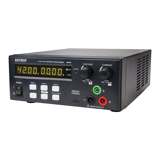
USER GUIDE Extech DCP42 160W Single Continuous Switching Power Supply Model DCP42 160W Laboratory Grade Constant Power, Switching Mode Power Supply actoolsupply.com... -
Page 2: Table Of Contents
5.2 Switching the Power Supply ON and Self-Test Information 5.3 Using the Control knobs 5.4 Connecting the Power Supply and running a Test 5.5 Keypad Lockout function 5.6 Manual Output ON/OFF 5.7 Ammeter/Wattmeter Selection SUPPLEMENTAL FUNCTIONS DCP42-EU-EN V1.2 9/13 actoolsupply.com... - Page 3 6.5.2 REMOTE CONTROL – METHOD 2: Using two 0 to 5K Ohm variable resistors 13 6.5.3 Remote Control Output ON/OFF PC SOFTWARE PROGRAM AUTOMATIC OUTPUT STEP PROGRAMS 8.1 External Timed Program Window 8.2 Output ON/OFF function 8.3 Automatic Timed Output Operation APPENDIX – ADDITIONAL OPERATIONAL EXAMPLES 10. SPECIFICATIONS 11. TROUBLESHOOTING DCP42-EU-EN V1.2 9/13 actoolsupply.com...
-
Page 4: Introduction And Features
A conventional power supply has only a set maximum voltage and current such that all of the operating V & A must fall within these limits. The DCP42 offers cost saving and space saving advantages as one constant-power power supply can do the work of several conventional power suppliers. -
Page 5: Safety
Before replacing the AC fuse, determine the cause and clear up the cause first Replace the AC fuse with the same type and rating as the original fuse The maximum output voltage of the DCP42 exceeds 60VDC, avoid touching the metal contact parts at the output terminals CAUTION ... -
Page 6: Power Supply Description
(9) Remote Sensing Terminal (Warning! Shorting the remote sensing terminal or Connect sensing terminal in reverse polarity will damage the power supply) (10) Remote Control Terminal (11) AC Inlet socket (with fuse holder) DCP42-EU-EN V1.2 9/13 actoolsupply.com... -
Page 7: Control Modes
Press the Menu key to exit the Set menu f. To start the ΔV/Δt function, press the SHIFT button and then press the ΔV/Δt button to run, g. To stop the ΔV/Δt function, press the SHIFT button and then press the ΔV/Δt button again. DCP42-EU-EN V1.2 9/13 actoolsupply.com... -
Page 8: Activating The Remote Control Mode
Press the Voltage control knob to confirm and to return to the Set menu. e. Press the Menu button to exit the Set menu. f. The Power Supply will reboot and revert to its Factory Default settings. DCP42-EU-EN V1.2 9/13 actoolsupply.com... -
Page 9: Operation
5. Operation Note: The DCP42 Total Output Voltage Range is 42VDC and the Total Rated Current is 0 to 10ADC 5.1 Powering the Supply Check the rating label of the power supply and ensure that it complies with the AC mains voltage that is to be used. -
Page 10: Supplemental Functions
Pressing “Preset 1” will now generate a ramp down voltage from 10V to 5V in 5 seconds and will remain at the 5V level. Note: The final output voltage level will be the last voltage level generated. DCP42-EU-EN V1.2 9/13 actoolsupply.com... -
Page 11: Function A/B/C Waveform Generator
A to B, then B to A. The waveform will repeat cyclically until SHIFT and then ΔV/Δt are pressed again. Examples 3, 4, and 5 are provided in Appendix A later in this guide. DCP42-EU-EN V1.2 9/13 actoolsupply.com... -
Page 12: Upper Voltage And Current Limits
The remote sensing wire should be AT LEAST 22AWG wire size. 6.4.2 Disconnection Warning! Incorrect disconnect sequences will damage the power supply 1. First disconnect the remote sensing connections. 2. Then disconnect the power connections between the power supply and equipment. DCP42-EU-EN V1.2 9/13 actoolsupply.com... -
Page 13: Remote Control Operation
Check the output voltage range of the power supply by adjusting the 5Kohm variable resistor. Short circuit the main output with 14AWG wire to check the CC setting on the display while adjusting the variable resistor. DCP42-EU-EN V1.2 9/13 actoolsupply.com... -
Page 14: Remote Control Output On/Off
The unit can be externally programmed via a PC to run 20 steps, each step with a preset voltage/current limiting value and a preset time period of 1 second to 99 minutes. The timed program can be set to run one cycle or up to an infinite number of cycles. DCP42-EU-EN V1.2 9/13 actoolsupply.com... -
Page 15: External Timed Program Window
7. Enter the number of desired running cycles. 8. Click [Run] to run the External Time Program. The External Timed Program feature allows the user to set the output either ON or OFF by selecting the boxes in the last column. DCP42-EU-EN V1.2 9/13 actoolsupply.com... -
Page 16: Appendix - Additional Operational Examples
Example 6 - Irregular waveform Set A = 5V, B = 10 V Set Δt a-b = 4 second, Set Δt b-a = 4 seconds Set Func. A = 2 seconds, Set Func .B = 2 seconds DCP42-EU-EN V1.2 9/13 actoolsupply.com... -
Page 17: Specifications
(230Vac / 100Vac): ≤220mA Full Load Input Current (230Vac / 100Vac): ≤1.0A / 2.3A Power Consumption (230Vac / 100Vac): ≤190W / 200W @ 42V / 3.8A Efficiency (230Vac / 100Vac): ≥86% / 84% @ 42V / 3.8A DCP42-EU-EN V1.2 9/13 actoolsupply.com... - Page 18 Case Material Polycarbonate Front Panel and Electro-Galvanized Steel Enclosure Case Protection IP20 Connection Dia. 4.0mm Safety Jack x3 (Output Positive, Negative and Function Ground) Dimensions (WxHxD) 200 x 90 x 250 mm (7.9 x 3.6 x 10 inch) Weight 2.5 kg (5.5 lb) DCP42-EU-EN V1.2 9/13 actoolsupply.com...
-
Page 19: Troubleshooting
actoolsupply.com 11. Troubleshooting OUP: Over Voltage Protection This unit has a built-in tracking over voltage protection feature. In the event of output voltage becoming greater than the set value (see specified range from specifications table), protection will be triggered and the output power will be cut off and OUP warning appears as below. To reset the warning, switch off the unit and remove all loading.
Need help?
Do you have a question about the DCP42 and is the answer not in the manual?
Questions and answers