Table of Contents
Advertisement
Quick Links
Advertisement
Table of Contents

Subscribe to Our Youtube Channel
Related Manuals for ANTAIRA BTS-1000A


Summary of Contents for ANTAIRA BTS-1000A
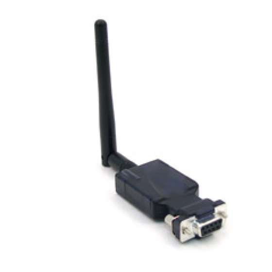
- Page 1 BTS-1000A Bluetooth to RS-232 Converter Operation Manual Version 1.0...
-
Page 2: Table Of Contents
………………………………………………………….. 3 3. Product Specification …………………………………………………... 4 4. Product Panel View Description ……………………………………. 5 BTS-1000A Product View …………………………………………………… 5 DC-In Power Outlet …………………………………………………………... 5 Antenna Connecter …………………………………………………………… 6 Serial I/O Port of RS-232 …………………………………………………….. 6 Synchronous Button …………………………………………………………... 6 LED Indicators ………………………………………………………………... 7 5. -
Page 3: Introduction
(Slave) 100 meters away without needing cables in your working environments. The BTS-1000A uses the frequency hopping and 128bit encryption in the 2.4 GHz frequency range to ensure a secure connection. Configuration and setup is very simple with the BTS-1000A. -
Page 4: Package Checklist
Package checklist The BTS-1000A is shipped with the following items: 1 x BTS-1000A Bluetooth to RS-232 Adapter with Antenna 1 x Power Adapter (5V DC, 200mA) Quick Installation Guide Setup Utility Software CD NOTE: Notify your sales representative if any of the above items are missing or... -
Page 5: Product Specification
Product Specification Serial Port No. of Ports: RS-232 * 1 Port ● Port Type: DB-9 female ● Speed: 1200 bps ~ 115.2K bps ● Parity: None , Odd , Even ● Data Bit: 8 ● Stop Bit: 1 , 2 ●... -
Page 6: Product Panel View Description
RS-232 DC-In Power Outlet The BTS-1000A Bluetooth to Serial Adapter is powered by a single 5V DC (Inner positive / outer negative) power supply and 200mA of current. A suitable power supply adapter is included in the packaging. Connect the power line to the power connector next to the antenna connector and plug the power adapter into a power outlet. -
Page 7: Antenna Connecter
(RS-232 RX/TX has been CROSSED OVER) Synchronous Button The Sync button is used to synchronize BTS-1000A devices using the BT RS232 Config Tool software. After setting the desired parameters and clicking the “Connect” button in the BT RS232 Config Tool software, use any point tip to push this button (located on the left side of the device) immediately. -
Page 8: Led Indicators
LED Indicators Red Color LED: Power indicator (When the power is on, the red color LED stay lit. Green Color LED: Before connecting to synchronize between the device and the BT RS232 Config Tool software, the green LED will be blinking. After connecting to synchronize between the device and the BT RS232 Config Tool software, the green &... -
Page 9: Hardware Installation
BTS-1000A Hardware Installation 1. Connect the BTS-1000A Bluetooth adapter to a COM Port of a PC and then connect the DC power adapter jack into a power outlet and DC-in outlet. You will see the red LED turn on and the green LED will blink. -
Page 10: Bt Rs232 Config Tool Installation & Setup
BT RS232 Config Tool Installation & Setup When setting up the BTS-1000A adapter for the first time, you have to install and run the BT RS232 Config Tool (BT1.EXE) first in your computer device. The utility CD is enclosed in the packaging. Before you use the BTS-1000A adapter, you have to pair the unit with another BTS-1000A device. -
Page 11: Bt Rs232 Config Tool Parameter Configuration
BT RS232 Config Tool Parameter Configuration Running the BT RS232 Config Tool, the configuration screen will pop-up as depicted above. A. COM Port Select a COM Port number, you have to avoid the ports that conflict with other devices in your computer and only use available ports. B. - Page 12 E. PIN Code The PIN Code is used for security like a pass key. The device uses this “PIN Code” to identify itself when connecting and establishing communication. F. Role The Role is used to identify the role of the device as either a master or slave.
-
Page 13: Apply "Connect
Apply “Connect” After configuring the parameters, click the “Connect” button while immediately pressing the Sync button located on the left side of the device. On the following screen, the “Connect” button should change to “Disconnect.” The “Read” and “Write” button will now be active on the bottom of the BT RS232 Config Tool screen. -
Page 14: Apply "Write
Apply “Write” Clicking “Write” will save all parameters configured using the BT RS232 Config Tool. Apply “Read” Clicking “Read” will load all parameters saved previously. The local address will be updated from the real device address initially. -
Page 15: Appendix A - Pin Outs And Cable Wiring
PIN 5: GND PIN 6: DTR PIN 7: CTS PIN 8: RTS PIN 9: DC 5V □ □ RS-232 Wiring Diagram □ Serial Device BTS-1000A Converter 2 RX 2 TX 3 TX 3 RX 5 GND 5 GND (Flow Control) 4 DTR...
Need help?
Do you have a question about the BTS-1000A and is the answer not in the manual?
Questions and answers