Table of Contents
Advertisement
Quick Links
Advertisement
Table of Contents

Related Manuals for ANTAIRA Optolinx IMP-100A


Summary of Contents for ANTAIRA Optolinx IMP-100A
- Page 1 10/100TX to 100FX w/ 1 PoE Injector Industrial Media Converter User Manual v1.02...
- Page 2 FCC Warning This Equipment has been tested and found to comply with the limits for a Class-A digital device, pursuant to Part 15 of the FCC rules. These limits are designed to provide reasonable protection against harmful interference in a residential installation. This equipment generates, uses, and can radiate radio frequency energy.
-
Page 3: Table Of Contents
Content Introduction ..............1 Features ..............1 Package Contents ............ 2 Hardware Description ..........3 Physical Dimension ..........3 Front Panel .............. 3 Top View ..............4 LED Indicators ............5 DIP-Switch ............... 6 Ports ................. 7 Cabling ..............9 Wiring the Power Inputs ......... -
Page 4: Introduction
Introduction The 1 10/100TX + 100FX w/ 1 PoE Injector Industrial Media Converter is a cost-effective solution and meets the high reliability requirements demanded by industrial applications. Use of the fiber port can extend the connection distance and increase the network elasticity and performance. -
Page 5: Package Contents
Package Contents Please refer to the package content list below to verify with package. 1 10/100TX + 100FX w/ 1 PoE Injector Industrial Media Converter User manual Pluggable Terminal Block 2 wall mount plates with screws ... -
Page 6: Hardware Description
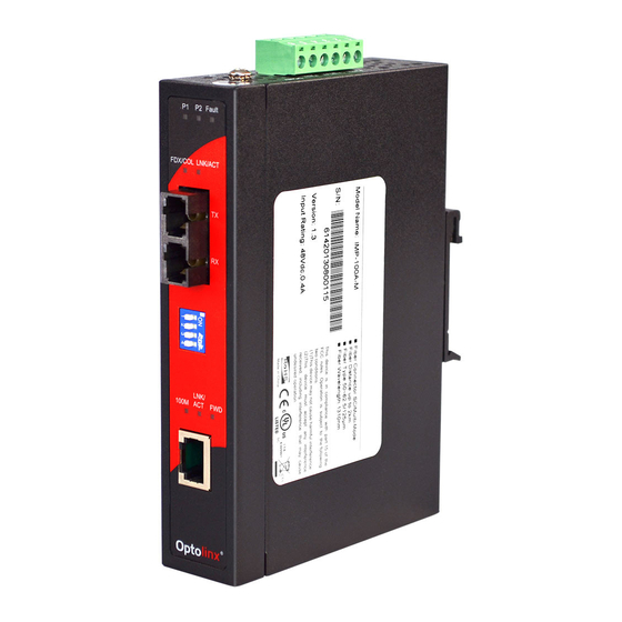
Hardware Description In this section, the Industrial Media Converter’s hardware specifications, port, cabling, and wiring installation will be provided. Physical Dimension 1 10/100TX + 100FX w/ 1 PoE Injector Industrial Media Converter dimension (W x D x H) is 30mm x 95mm x 140mm Front Panel The Front Panel of the 1 10/100TX + 100FX w/ 1 PoE Injector Industrial Media Converter is shown as below:... -
Page 7: Top View
Top View The top view of the 1 10/100TX + 100FX w/ 1 PoE Injector Industrial Media Converter has one terminal block connector of two DC power inputs. Top View of the PoE Injectors Industrial Media Converter... -
Page 8: Led Indicators
LED Indicators The diagnostic LEDs located on the front panel of the industrial media converter provide real-time system information and optional status. The table below describes the LED status and their meaning for the media converter. Color Description Power input 1 is active Green Power input 1 is inactive Power input 2 is active... -
Page 9: Dip-Switch
DIP-Switch The DIP-Switch is used to configure operation mode for LLF (Link Loss Forwarding)/LFP (Link Fault Pass-Through), and operation mode for UTP/Fiber port. The default value of the DIP-switch is OFF. S/W No Status Description Enables Port/Power Alarm Disable Port/Power Alarm Enables LLF/LFP Disables LLF/LFP 100Base-FX Half-mode... -
Page 10: Ports
Ports RJ-45 ports The UTP (RJ-45) Fast Ethernet ports will auto-sense 10Base-T or 100Base-TX connections. Auto MDI/MDIX means that the media converter can connect to another switch or workstation without changing straight through or crossover cabling. See the figures below for straight through and crossover cable schematic. ... - Page 11 Straight Through Cable Schematic Cross Over Cable Schematic Fiber Port The fiber port is an SC type connector that is either multi mode (2Km) or single mode (30Km). When you connect the fiber port to another device, please follow the figure below to connect accordingly.
-
Page 12: Cabling
Cabling Twisted-pair segments can be connected with unshielded twisted pair (UTP) or shielded twisted pair (STP) cable. The cable must comply with the IEEE 802.3u 100Base TX standard for Category 5. The cable between the converter and the link partner (switch, hub, workstation, etc.) must be less than 100 meters (328 ft.) long. -
Page 13: Wiring The Power Inputs
Wiring the Power Inputs Please follow the steps below to insert the power wires. Insert the positive and negative wires into the V+ and V- contacts on the terminal block connector. Tighten the wire-clamp screws to prevent wires from loosening. -
Page 14: Wiring The Fault Alarm Contact
Wiring the Fault Alarm Contact The fault alarm contacts are in the middle of terminal block connector as the picture shows below. Inserting the wires, it will detect the fault status including power failure or port link failure (managed industrial switch only) and form an open circuit. An application example for the fault alarm contact is shown below: Insert the wires into the fault alarm contacts. -
Page 15: Mounting Installation
Mounting Installation DIN-Rail Mounting The DIN-Rail is pre-screwed on the industrial media converter from the factory. If the DIN-Rail is not screwed on the unit, please follow the instructions below on how to install the DIN-Rail on the unit. Follow the steps below to mount the industrial media converter. Use the screws to install the DIN-Rail on the rear side of the unit. - Page 16 After the DIN-Rail is screwed on the rear side of the unit, insert the top of DIN-Rail into the track. Then, lightly push the DIN-Rail into the track. Check if the DIN-Rail is securely mounted on the track. To remove the industrial media converter from the track, reverse steps above.
-
Page 17: Wall Mount Plate Mounting
Wall Mount Plate Mounting Follow the steps below to mount the industrial media converter with wall mount plate. 1. Remove the DIN-Rail from the industrial media converter; loosen the screws to remove the DIN-Rail. 2. Place the wall mount plate on the top & bottom side of the industrial media converter. 3. -
Page 18: Hardware Installation
Hardware Installation In this section, instructions on how to install the 1 10/100TX + 100FX w/ 1 PoE Injector Industrial Media Converter will be provided. Installation Steps 1. Unpack the Industrial Media Converter. 2. Check if the DIN-Rail is installed on the Industrial Media Converter. If the DIN-Rail is not attached on the Industrial Media Converter, please refer to the DIN-Rail Mounting section for DIN-Rail installation. -
Page 19: Network Application
Network Application This segment provides an example to help users understand an industrial media converter application. For a sample application using the industrial media converter, see figure below. -
Page 20: Troubles Shooting
Troubles shooting Verify that the right power cord/adapter (DC 48V) is being used, please do not use a power adapter with DC output voltage higher than 48V, or it will burn the converter. Select the proper UTP/STP cable to construct your network. Please check that the right cable is being used. -
Page 21: Technical Specification
Technical Specification The 1 10/100TX + 100FX w/ 1 PoE Injector Industrial Media Converter technical specifications are shown below. IEEE 802.3 10Base-T Ethernet IEEE 802.3u 100Base-TX/FX Standard IEEE802.3x Flow Control and Back Pressure IEEE802.3af Power over Ethernet Protocol CSMA/CD 14,880 pps for 10Base-T Ethernet port Transfer Rate 148,800 pps for 100Base-TX/FX Fast Ethernet port 10/100TX: 1 x RJ-45 with auto MDI/MDI-X function;... - Page 22 10Base-T: 2-pair UTP/STP Cat. 3, 4, 5, 5e cable EIA/TIA-568 100-ohm (100m) Network Cable 100Base-TX: 2-pair UTP/STP Cat. 5/5E cable EIA/TIA-568 100-ohm (100m) Multi mode: 50/125μm ~ 62.5/125μm Single mode: 9/125μm Optical cable Available distance: 2km (multi-mode)/30km (single-mode) Wavelength: 1310nm (Multi-mode/Single-mode) Redundant power DC 48V with connective removable Power Supply terminal block...
- Page 23 IEC60068-2-32 (Free fall) Stability testing IEC60068-2-27 (Shock) IEC60068-2-6 (Vibration)
Need help?
Do you have a question about the Optolinx IMP-100A and is the answer not in the manual?
Questions and answers