Table of Contents
Advertisement
Quick Links
Advertisement
Table of Contents

Related Manuals for ANTAIRA IMC-1000A-SFP


Summary of Contents for ANTAIRA IMC-1000A-SFP
- Page 1 10/100/1000BaseT to Mini-GBIC Industrial Media Converter User Manual...
-
Page 2: Table Of Contents
Content Overview ............1 Introduction .............. 1 Features ..............3 Packing List .............. 4 Safety Precaution ............. 4 Hardware Description ......... 5 Front Panel ............... 5 Top View ..............6 Wiring the Power Inputs ........... 6 Wiring the Fault Alarm Contact ........ 7 LED Indicators ............ - Page 3 Hardware Installation ........18 Installation Steps ............ 18 Troubles shooting ..........20 Technical Specification ........21...
- Page 4 FCC Warning This Equipment has been tested and found to comply with the limits for a Class-A digital device, pursuant to Part 15 of the FCC rules. These limits are designed to provide reasonable protection against harmful interference in a residential installation. This equipment generates, uses, and can radiate radio frequency energy.
-
Page 5: Overview
Overview Introduction The 10/100/1000TX to MINI-GBIC is designed to convert Gigabit Ethernet networks to Gigabit fiber networks by transparently converting Ethernet signals to optic signals. The advantages of fiber optics are wide bandwidth, EMI immunity and long-distance transmission capability. Therefore, the industrial switch converter is an ideal solution for “fiber to building”... - Page 6 Flexible Mounting 10/100/1000TX to MINI-GBIC Industrial Switch Converter is compact and can be mounted on a DIN-rail or a panel, so it is suitable for any space-constrained environment. Advanced Protection The power line of 10/100/1000TX to MINI-GBIC Industrial Switch Converter supports up to 3,000 V EFT protection, which secure equipment against unregulated voltage and make systems safer and more reliable.
-
Page 7: Features
Features Provides 1 x SFP (mini-GBIC) type socket Provides 1 x 10/100/1000Mbps Ethernet ports with RJ-45 connector Supports full/half duplex flow control Supports MDI/MDI-X auto-crossover Supports surge (EFT) protection 3,000 V for power line Supports 6,000 V Ethernet ESD protection ... -
Page 8: Packing List
Packing List 1 x 10/100/1000 to Mini-GBIC Industrial Switch Converter 1 x User manual 2 x Wall Mounting Bracket and Screws Safety Precaution Attention IF DC voltage is supplied by an external circuit, please use a protection device on the power supply input. -
Page 9: Hardware Description
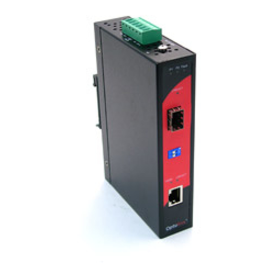
Hardware Description In this paragraph, we will introduce the Industrial switch converter’s hardware spec, port, cabling information, and wiring installation. Front Panel The Front Panel of the 10/100/1000TX to MINI-GBIC Industrial Switch Converter are shown as below. Front Panel of the Industrial Switch Converter... -
Page 10: Top View
Top View The top panel of the Industrial Switch Converter is equipped one terminal block connector of two DC power inputs. Top panel of the Industrial Switch Converter Wiring the Power Inputs Please follow the steps below to insert the power wire. 1. -
Page 11: Wiring The Fault Alarm Contact
2. To tighten the wire-clamp screws for preventing the DC wires to loose. Wiring the Fault Alarm Contact The fault alarm contact is in the middle of terminal block connector as the picture shows below. Inserting the wires, it will detect the fault status which the power is failure or port link failure (for managed model) and form an open circuit. -
Page 12: Led Indicators
LED Indicators There are few LEDs display the power status and network status located on the front panel of the Industrial switch converter, each of them has its own specific meaning as below table. Table 2.1: Industrial Switch Converter LED Definition Color Description Power input 1 is active... -
Page 13: Dip-Switch
DIP-Switch The DIP-Switch is used to configure operation mode for LLF (Link Lost Forwarding) and power alarm. The default value of DIP-switch is OFF. Table 2.2: Industrial Switch Converter DIP-Switch Definition S/W No Status Description Enable Power Alarm Disable Power Alarm Enables LLF Disables LLF Link Lost Forwarding (DIP-Switch 2): When LLF is enabled, it allows... -
Page 14: Ports
Ports RJ-45 ports (Auto MDI/MDIX): The RJ-45 ports are auto-sensing for 10Base-T, 100Base-TX or 1000Base-T devices connections. Auto MDI/MDIX means that you can connect to another switch or workstation without changing straight through or crossover cabling. See figures as below for straight through and crossover cable schematic. ... -
Page 15: Cabling
Straight Through Cable Schematic Cross Over Cable Schematic Cabling Twisted-pair segment can use unshielded twisted pair (UTP) or shielded twisted pair (STP) cabling. The cable between the link partner (switch, hub, workstation, etc.) and the converter must be less than 100 meters (328 ft.) long and comply with the IEEE 802.3ab 1000Base-T standard for Category 5e or above. - Page 16 Figure 2.8: Transceiver to the SFP module Figure 2.9: Transceiver Inserted...
- Page 17 Second, insert the fiber cable of LC connector into the transceiver. Figure 2.10: LC connector to the transceiver To remove the LC connector from the transceiver, please follow the steps shown below: First, press the upper side of the LC connector from the transceiver and pull it out to release.
- Page 18 Second, push down the metal loop and pull the transceiver out by the plastic part. Figure 2.12: Pull out from the SFP module...
-
Page 19: Mounting Installation
Mounting Installation DIN-Rail Mounting The DIN-Rail is screwed on the industrial switch when out of factory. If the DIN-Rail is not screwed on the industrial switch, please see the following figure to screw the DIN-Rail on the switch. Follow the below steps to hang the industrial switch. - Page 20 First, insert the top of DIN-Rail into the track. Then, lightly push the button of DIN-Rail into the track. Check the DIN-Rail is tightly on the track. To remove the industrial switch from the track, reverse steps above.
-
Page 21: Wall Mount Plate Mounting
Wall Mount Plate Mounting Follow the steps below to mount the industrial switch with wall mount plate. Remove the DIN-Rail from the industrial switch; loose the screws to remove the DIN-Rail. Place the wall mount plate on the rear panel of the industrial switch. Use the screws to screw the wall mount plate on the industrial switch. -
Page 22: Hardware Installation
Hardware Installation In this paragraph, we will describe how to install the 5-port 10/100/1000Base-TX Industrial Switch Converter and the installation points for the attention. Installation Steps Unpacked the Industrial switch converter packing. Check the DIN-Rail is screwed on the Industrial switch converter. If the DIN-Rail is not screwed on the Industrial switch converter. - Page 23 Power on the Industrial switch converter. How to wire the power; please refer to the Wiring the Power Inputs section. The power LED on the Industrial switch converter will light up. Please refer to the LED Indicators section for meaning of LED lights. Prepare the twisted-pair, straight through Category 5 cable for Ethernet connection.
-
Page 24: Troubles Shooting
Troubles shooting Verify that you are using the right power cord/adapter (DC 12 ~ 48V), please don’t use the power adapter with DC output higher than 48V, or it will burn this switch converter down. Select the proper UTP cable to construct your network. Please check that you are using the right cable. -
Page 25: Technical Specification
Technical Specification The technical specifications of the Industrial Switch Converter are listed as follows. Communications IEEE 802.3, 802.3ab, 802.3u, 802.3x, Standard 802.3z 10/100/1000Base-TX Transmission Distance SFP (mini-GBIC) Fiber: Up to 110km Ethernet: Up to 100 meters (STP or UTP) Up to 1000 Mbps Transmission Speed Interface Connectors... - Page 26 Mechanism Dimensions (WxDxH) 30 x 95 x 140 mm Enclosure IP30, Metal shell with solid mounting kits Mounting DIN-rail, wall Protection 6,000 V ESD (Ethernet) Surge (EFT for power) 3,000 V Reverse Polarity Present Overload 0.9A@12V Environment Operating Temperature Standard model: -10 ~ 60 Wide temp.
- Page 27 CE EN61000-4-6 (CS) CE EN61000-4-8 CE EN61000-4-11 CE EN61000-4-12 CE EN61000-6-2 CE EN61000-6-4 IEC60068-2-32 Free Fall Shock IEC60068-2-27 Vibration IEC60068-2-6...
Need help?
Do you have a question about the IMC-1000A-SFP and is the answer not in the manual?
Questions and answers