Sign In
Upload
Manuals
Brands
IEI Technology Manuals
Industrial PC
DRPC-120-BT
User Manuals: IEI Technology DRPC-120-BT DIN Rail PC
Manuals and User Guides for IEI Technology DRPC-120-BT DIN Rail PC. We have
1
IEI Technology DRPC-120-BT DIN Rail PC manual available for free PDF download: User Manual
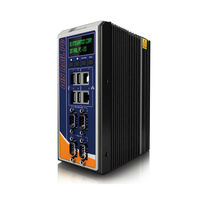
IEI Technology DRPC-120-BT User Manual (121 pages)
DIN RAIL PC, Fanless embedded system
Brand:
IEI Technology
| Category:
Desktop
| Size: 4 MB
Table of Contents
User Manual
1
Table of Contents
4
1 Introduction
13
Figure 1-1: DRPC-120-Bti Series
14
Figure 1-2: DRPC-120-Bti-E5-LED Front Panel
16
Figure 1-4: DRPC-120-Bti Top Panel
18
Figure 1-5: LED Indicators of DRPC-120-Bti-E5-LED
18
LED Indicators (DRPC-120-Bti-E5-LED Only)
18
Programmable OLED Display (DRPC-120-Bti-E5-OLED Only)
19
Table 1-2: DRPC-120-Bti-E5-LED LED Definitions
19
Technical Specifications
19
Table 1-3: Technical Specifications
21
Dimensions
22
Figure 1-3: DRPC-120-Bti-E5-OLED Front Panel
17
Top Panel
17
Model Variations
14
Overview
14
Table 1-1: DRPC-120-Bti Model Variations
14
Features
15
Connector Panel
16
Front Panel
16
Figure 1-6: Physical Dimensions (Millimeters)
22
2 Unpacking
23
Anti-Static Precautions
24
Unpacking Precautions
24
Unpacking Checklist
25
3 Installation
28
Installation Precautions
29
High Surface Temperature
29
Figure 3-1: Internal Access Panel Removal
30
Hdd Installation
30
Internal Access Panel Removal
30
Figure 3-2: HDD Installation
31
Figure 3-5: Securing the Pcie Mini Card
33
Figure 3-6: IPMI Module Slot Location
34
Figure 3-7: IPMI Module Installation
34
Figure 3-8: Clear CMOS Button Location
35
At/Atx Mode Selection
36
Figure 3-10: DIN Rail Mounting Bracket Installation
36
Figure 3-9: AT/ATX Switch Location
36
Mounting the System
36
Figure 3-11: Attach the Mounting Bracket to the DIN Rail
37
External Peripheral Interface Connectors
38
Figure 3-12: Mounting the System
38
Digital Input/Output Terminal Block
39
LAN Connectors
39
Clear Cmos
35
Msata Ssd Installation
31
Figure 3-3: Pcie Mini Slot Location
32
Figure 3-4: Inserting the Pcie Mini Card into the Socket
32
IPMI Module Installation (Optional)
33
Figure 3-13: DIO Terminal Block Pinout Location
39
Figure 3-14: RJ-45 Ethernet Connector
40
Table 3-2: LAN1 Pinouts
40
Table 3-3: LAN2 Pinouts
40
Table 3-4: RJ-45 Ethernet Connector Leds
40
Figure 3-15: 3-Pin Power Terminal Block Pinout Location
41
Figure 3-16: RS-232 Serial Port Pinout Location
42
Table 3-6: RS-232 Serial Port Pinouts
42
RS-422/485 Serial Port Connectors (COM3, COM4)
43
Table 3-7: RS-422/485 Serial Port Pinouts
43
USB Connectors
44
Table 3-5: 3-Pin Power Terminal Block Pinouts
41
Serial Port Connectors (COM1, COM2)
42
Figure 3-17: RS-422/485 Serial Port Pinout Locations
43
Table 3-8: USB 2.0 Port (USB3/USB4) Pinouts
44
Table 3-9: USB 3.0 Port (USB1/USB2) Pinouts
44
Figure 3-18: VGA Connector
45
Table 3-10: VGA Connector Pinouts
45
Figure 3-19: IEI Iman Web Address
46
Managed System Hardware Setup
46
Using the IEI Iman Web GUI
46
Figure 3-20: IEI Iman Web GUI
47
Driver Installation
48
Ipmi Setup Procedure
45
VGA Connector
45
Table 3-1: DIO Terminal Block Pinouts
39
Power Input, 3-Pin Terminal Block
41
4 System Maintenance
49
System Maintenance Introduction
50
Motherboard Replacement
50
So-DIMM Replacement
51
Figure 4-1: SO-DIMM Module Location
51
Figure 4-2: SO-DIMM Module Installation
52
5 Bios
53
Introduction
54
Starting Setup
54
Using Setup
54
Getting Help
55
Unable to Reboot after Configuration Changes
55
BIOS Menu Bar
55
Table 5-1: BIOS Navigation Keys
55
Main
56
Advanced
58
ACPI Settings
59
Super IO Configuration
60
Serial Port N Configuration
61
Iwdd H/W Monitor
66
Smart Fan Mode Configuration
67
RTC Wake Settings
69
Serial Port Console Redirection
70
CPU Configuration
72
IDE Configuration
75
USB Configuration
76
Chipset
77
North Bridge
78
South Bridge
78
PCI Express Configuration
80
Security
81
Boot
82
Exit
84
6 Programming Oled for Drpc-120-Bti-E5-Oled
86
Oled Image Editor
87
OLED Image Editor Installation
87
Overview
87
Figure 6-2: Select Installation Folder
88
Figure 6-3: Confirm Installation
89
Figure 6-5: OLED Image Editor
90
Figure 6-6: Function List
90
Figure 6-7: OLED Control
91
Figure 6-8: OLED Erase Page
92
OLED Erase Page
92
Drpc100 Demo Program
93
Figure 6-9: DR100 Demo Program Main Menu
93
Dialog Menu
94
Figure 6-10: Dialog Menu
94
Figure 6-11: LCD Menu
95
LCD Menu
95
DEMO Menu
96
OLED Control
91
Figure 6-1: OLED Image Editor Setup Wizard
88
Figure 6-4: Installation Complete
89
Function List
90
Launching the OLED Image Editor
90
Figure 6-12: DEMO Menu
96
7 Interface Connectors
97
Figure 7-1: Main Board Layout Diagram (Front Side)
98
Figure 7-2: Main Board Layout Diagram (Solder Side)
98
DRPC-120-Bti
99
Audio Line-Out Connector (LINE_OUT1)
100
Audio MIC-In Connector (MIC_IN1)
100
Battery Connector (BAT1)
100
Chassis Intrusion Connector (CHASSIE1)
100
Table 7-1: Peripheral Interface Connectors
99
Peripheral Interface Connectors
98
Internal Peripheral Connectors
99
Table 7-4: Battery Connector (BAT1) Pinouts
100
Table 7-2: Audio Line-Out Connector (LINE_OUT1) Pinouts
100
Table 7-3: Audio MIC-In Connector (MIC_IN1) Pinouts
100
Table 7-5: Chassis Intrusion Connector (CHASSIE1) Pinouts
100
Table 7-6: CPU Fan Connector (CPU_FAN1) Pinouts
101
Table 7-7: OLED/LED Signal Connector (OLED1) Pinouts
101
Table 7-8: Pcie Mini Card Slot - Full Size (M_PCIE1) Pinouts
102
SATA 3Gb/S Connector (SATA1)
103
Table 7-10: SATA 3Gb/S Connector (SATA1) Pinouts
103
Table 7-9: Pcie Mini Card Slot - Half Size (MINI-PCIE1) Pinouts
103
SATA Power Connector (SATA_PWR1)
104
SPI Flash Connector (JSPI1)
104
SPI Flash Connector - EC (JSPI2)
104
Table 7-11: SATA Power Connector (SATA_PWR1) Pinouts
104
Table 7-12: SPI Flash Connector (JSPI1) Pinouts
104
Table 7-13: SPI Flash Connector - EC (JSPI2) Pinouts
104
Table 7-14: USB Connector (USB1) Pinouts
105
Table 7-15: Rear Panel Connectors
105
USB Connector (USB1)
105
Digital I/O Terminal Block (J1)
106
LAN Connector (LAN1)
106
Power Input Terminal Block (DC_IN1)
106
Table 7-16: Digital I/O Terminal Block (J1) Pinouts
106
Table 7-17: Power Input Terminal Block (DC_IN1) Pinouts
106
Table 7-18: RJ-45 LAN Connector (LAN1) Pinouts
106
LAN Connector (LAN2)
107
RS-422/485 Serial Ports (COM3/4)
107
Serial Ports (COM1/2)
107
Table 7-19: RJ-45 LAN Connector (LAN2) Pinouts
107
Table 7-20: RS-232 Serial Port (COM1/2) Pinouts
107
Table 7-21: RS-422/485 Serial Port (COM3/4) Pinouts
107
Table 7-22: USB 2.0 Connectors (USB2) Pinouts
108
Table 7-23: USB 3.0 Connectors (USB1) Pinouts
108
USB 2.0 Connectors (USB2)
108
USB 3.0 Connectors (USB1)
108
VGA Connector (VGA1)
108
Table 7-24: VGA Connector (VGA1) Pinouts
109
Pcie Mini Card Slot - Half Size (MINI-PCIE1)
102
External Interface Panel Connectors
105
CPU Fan Connector (CPU_FAN1)
101
OLED/LED Signal Connector (OLED1)
101
Pcie Mini Card Slot - Full Size (M_PCIE1)
101
A Safety Precautions
110
Safety Precautions
111
General Safety Precautions
111
Anti-Static Precautions
112
Explanation of Graphical Symbols
112
Product Disposal
113
Maintenance and Cleaning Precautions
113
Maintenance and Cleaning
113
Cleaning Tools
114
B Digital I/O Interface
115
Introduction
116
B.1 I Ntroduction
116
Assembly Language Sample 1
117
Assembly Language Sample 2
117
C Hazardous Materials Disclosure
118
Hazardous Materials Disclosure Table for IPB Products Certified as Rohs Compliant under 2002/95/EC Without Mercury
119
Advertisement
Advertisement
Related Products
IEI Technology DRPC-230-ULT5-CE/8G/S
IEI Technology DRPC-120-BTi-E5-LED/2G
IEI Technology DRPC-120-BTi-E5-OLED/2G
IEI Technology DRPC-130-AL
IEI Technology DRPC-120-BTi
IEI Technology DRPC-100
IEI Technology DRPC-124-EHL Series
IEI Technology DRPC-124-EHL-JC-R10
IEI Technology DRPC-140-EHL Series
IEI Technology DRPC-100-CV-LED-R10
IEI Technology Categories
Motherboard
Touch Panel
Computer Hardware
Single board computers
Desktop
More IEI Technology Manuals
Login
Sign In
OR
Sign in with Facebook
Sign in with Google
Upload manual
Upload from disk
Upload from URL