Table of Contents
Advertisement
Quick Links
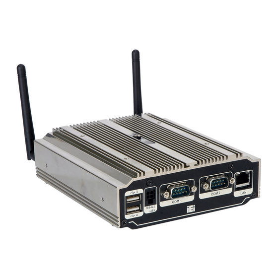
uIB X-210-C V-N2600 E mbedded S ys tem
,
MODE L :
uIB X-210-C V-N2600 S eries
F anles s E mbedded S ys tem with Intel® A tom™ N2600
DC 1.6G Hz, Intel® NM10 c hips et, P re-ins talled 2G B DDR 3
memory, V G A , HDMI, G bE , F our US B 2.0,
T hree C OM and R oHS C ompliant
Us er Manual
P age i
R ev. 1.02 – 14 J une 2018
Advertisement
Table of Contents

Related Manuals for IEI Technology uIBX-210-CV-N2600 Series


Summary of Contents for IEI Technology uIBX-210-CV-N2600 Series
- Page 1 uIB X-210-C V-N2600 E mbedded S ys tem MODE L : uIB X-210-C V-N2600 S eries F anles s E mbedded S ys tem with Intel® A tom™ N2600 DC 1.6G Hz, Intel® NM10 c hips et, P re-ins talled 2G B DDR 3 memory, V G A , HDMI, G bE , F our US B 2.0, T hree C OM and R oHS C ompliant Us er Manual...
- Page 2 uIB X-210-C V-N2600 E mbedded S ys tem R evis ion Date Version Changes 14 June 2018 1.02 Add Table 3-1: RS-422/485 Serial Port Pinouts Add Table 3-2: RS-422/485 Connector Pinouts (DB-9) 28 February 2013 1.01 Update Section 2.3: Packing List 27 December 2012 1.00 Initial release...
- Page 3 uIB X-210-C V-N2600 E mbedded S ys tem C opyright C OP Y R IG HT NOT IC E The information in this document is subject to change without prior notice in order to improve reliability, design and function and does not represent a commitment on the part of the manufacturer.
- Page 4 uIB X-210-C V-N2600 E mbedded S ys tem Manual C onventions WAR NING Warnings appear where overlooked details may cause damage to the equipment or result in personal injury. Warnings should be taken seriously. C AUT ION Cautionary messages should be heeded to help reduce the chance of losing data or damaging the product.
-
Page 5: Table Of Contents
uIB X-210-C V-N2600 E mbedded S ys tem Table of C ontents 1 INTRODUCTION ......................2 1.1 O ........................3 VERVIEW 1.2 M ..................... 3 ODEL ARIATIONS 1.3 F ........................4 EATURES 1.4 T ..................4 ECHNICAL PECIFICATIONS 1.5 F ...................... - Page 6 uIB X-210-C V-N2600 E mbedded S ys tem 3.8.4 RS-232 Serial Port Connection ................ 29 3.8.5 RS-422/485 Serial Port Connection ..............30 3.8.6 USB Device Connection ................... 32 3.8.7 VGA Monitor Connection ................33 3.9 D ....................34 RIVER OWNLOAD 4 SYSTEM MOTHERBOARD ..................
- Page 7 uIB X-210-C V-N2600 E mbedded S ys tem 5.3 T ....................47 URN OFF THE OWER 5.4 R ..................47 EPLACING OMPONENTS 5.4.1 Hard Disk Drive (HDD) Replacement ............. 47 5.4.2 Memory Module Replacement ................. 50 5.4.3 WLAN Card Replacement ................51 6 BIOS ..........................
- Page 8 uIB X-210-C V-N2600 E mbedded S ys tem B SAFETY PRECAUTIONS ................... 89 B.1 S ....................90 AFETY RECAUTIONS B.1.1 General Safety Precautions ................90 B.1.2 Anti-static Precautions ..................91 B.1.3 Product Disposal ..................... 92 B.2 M ............92 AINTENANCE AND LEANING RECAUTIONS B.2.1 Maintenance and Cleaning ................
- Page 9 uIB X-210-C V-N2600 E mbedded S ys tem L is t of F igures Figure 1-1: uIBX-210-CV-N2600 ..................... 3 Figure 1-2: uIBX-210-CV-N2600 Front Panel ................6 Figure 1-3: uIBX-210-CV-N2600 Rear Panel ................. 7 Figure 1-4: Physical Dimensions (mm) ..................8 Figure 3-1: Wi-Fi Antenna Installation ..................14 Figure 3-2: AT/ATX Switch Location ...................14 Figure 3-3: Reset Button Location ....................16...
- Page 10 uIB X-210-C V-N2600 E mbedded S ys tem Figure 3-27: RS-422/485 Serial Port (DB-9) ................31 Figure 3-28: USB Device Connection ..................33 Figure 3-29: VGA Connector .......................34 Figure 4-1: System Motherboard ....................37 Figure 5-1: Retention Screws Removal ..................47 Figure 5-2: HDD Bracket Retention Screws ................48 Figure 5-3: HDD Bracket ......................48 Figure 5-4: HDD Retention Screws .....................49 Figure 5-5: Remove the old HDD ....................49...
- Page 11 uIB X-210-C V-N2600 E mbedded S ys tem L is t of Tables Table 1-1: Model Variations ......................3 Table 1-2: Technical Specifications ....................6 Table 2-1: Package List Contents ....................11 Table 3-1: RS-422/485 Serial Port Pinouts .................31 Table 3-2: RS-422/485 Connector Pinouts (DB-9) ..............32 Table 4-1: Peripheral Interface Connectors ................38 Table 4-2: Battery Connector Pinouts (BAT1) ................38 Table 4-3: BIOS Programming Connector Pinouts (SPI1) ............38...
- Page 12 uIB X-210-C V-N2600 E mbedded S ys tem B IOS Menus BIOS Menu 1: Main ........................57 BIOS Menu 2: Advanced ......................58 BIOS Menu 3: ACPI Configuration ....................59 BIOS Menu 4: RTC Wake Settings ....................60 BIOS Menu 5: CPU Configuration ....................61 BIOS Menu 6: IDE Configuration ....................62 BIOS Menu 7: USB Configuration ....................63 BIOS Menu 8: Super IO Configuration..................64...
-
Page 13: Introduction
uIB X-210-C V-N2600 E mbedded S ys tem C hapter Introduc tion P age 2... -
Page 14: Overview
2 GB. The uIBX-210-CV-N2600 supports a 2.5” SATA HDD with up to 3 Gb/s data transfer rate. Three serial ports and four external USB 2.0 ports ensure simplified connectivity to a variety of external peripheral devices. 1.2 Model Variations The model variations of the uIBX-210-CV-N2600 series are listed below. Models Wireless uIBX-210-CV-N2600/2GB-R10 Intel®... -
Page 15: Features
uIB X-210-C V-N2600 E mbedded S ys tem 1.3 F eatures The uIBX-210-CV-N2600 features are listed below: Slim and compact embedded system design with Intel® 3rd Gen Atom N2600 dual-core processor , Supports DDR3 memory (System Max. 2GB) 12V only single voltage design, supports AT/ATX power mode selection ... - Page 16 uIB X-210-C V-N2600 E mbedded S ys tem S ys tem F unc tion Support HDMI, VGA for dual independent display Dis play Output Display 1: Analog CRT up to 1920x1200 for Cedarview-D and Cedarview-M, support CRT hot plug Display 2: HDMI up to 1920 x 1200 1 x RJ-45 LAN by Realtek RTL8111E GbE E thernet Fintek F81866...
-
Page 17: Front Panel
uIB X-210-C V-N2600 E mbedded S ys tem Fintek F81865 Hardware Monitor 0°C ~ 50°C with air flow Operating T emperature VESA 75 Mounting CE, FCC class A E MC /S afety Microsoft® WES7E S upported OS Microsoft® Windows® XP Embedded Microsoft®... -
Page 18: Figure 1-3: Uibx-210-Cv-N2600 Rear Panel
uIB X-210-C V-N2600 E mbedded S ys tem 1 x AT/ATX Switch 1 x HDD LED 1 x HDMI port 1 x Line out 1 x Mic 1 x Power button 1 x Power LED ... -
Page 19: Dimensions
uIB X-210-C V-N2600 E mbedded S ys tem 1.7 Dimens ions The physical dimensions are shown below: Figure 1-4: Physical Dimensions (mm) P age 8... -
Page 20: Unpacking
uIB X-210-C V-N2600 E mbedded S ys tem C hapter Unpac king P age 9... -
Page 21: Anti - Static Precautions
uIB X-210-C V-N2600 E mbedded S ys tem 2.1 Anti-s tatic P recautions WAR NING : Failure to take ESD precautions during installation may result in permanent damage to the uIBX-210-CV-N2600 and severe injury to the user. Electrostatic discharge (ESD) can cause serious damage to electronic components, including the uIBX-210-CV-N2600. -
Page 22: Packing List
uIB X-210-C V-N2600 E mbedded S ys tem 2.3 P ac king L is t NOT E : If some of the components listed in the checklist below are missing, please do not proceed with the installation. Contact the IEI reseller or vendor you purchased the uIBX-210-CV-N2600 from or contact an IEI sales representative directly. -
Page 23: Installation
uIB X-210-C V-N2600 E mbedded S ys tem C hapter Ins tallation P age 12... -
Page 24: Installation Precautions
S tep 0: 3.3 Wi-F i Antenna Ins tallation (Wi-F i Model Only) To install the Wi-Fi antennas to the uIBX-210-CV-N2600 series for efficient wireless network transmission, follow the steps below. Locate the antenna connectors on the rear panel of the embedded system. -
Page 25: At/Atx Mode Selection
uIB X-210-C V-N2600 E mbedded S ys tem Install the antennas to the antenna connectors ( F igure 3-1). S tep 2: 7 6 7 H 7 6 7 H Figure 3-1: Wi-Fi Antenna Installation 3.4 AT /AT X Mode S elec tion AT or ATX power mode can be used on the uIBX-210-CV-N2600. -
Page 26: At Power Mode
uIB X-210-C V-N2600 E mbedded S ys tem 3.4.1 AT P ower Mode With the AT mode selected, the power is controlled by a central power unit rather than a power switch. The uIBX-210-CV-N2600 panel PC turns on automatically when the power is connected. -
Page 27: Powering O N The System
uIB X-210-C V-N2600 E mbedded S ys tem Figure 3-3: Reset Button Location Press the reset button. S tep 2: S tep 0: 3.6 P owering On the S ys tem To power on the system, follow the steps below: Press the power button on the front panel (Figure 3-4). -
Page 28: Wall Mount
uIB X-210-C V-N2600 E mbedded S ys tem 3.7.1 Wall Mount To mount the embedded system onto a wall using the optional VESA 75 wall mount kit, please follow the steps below. Select the location on the wall for the wall-mounting bracket. S tep 1: Carefully mark the locations of the four brackets screw holes on the wall. -
Page 29: Figure 3-6: Chassis Support Screws
uIB X-210-C V-N2600 E mbedded S ys tem Carefully insert the screws through the holes and gently pull the system S tep 8: downwards until the system rests securely in the slotted holes (Figure 3-6). Ensure that all four of the mounting screws fit snuggly into their respective slotted holes. -
Page 30: Vesa Mount 75
uIB X-210-C V-N2600 E mbedded S ys tem Figure 3-7: Secure the uIBX-210-CV-N2600 3.7.2 V E S A mount 75 To mount the embedded system onto a panel PC (VESA 75 mm), please follow the steps below. Figure 3-8: Panel PC (VESA 75 mm) P age 19... -
Page 31: Figure 3-9: Mount Kit Installation
uIB X-210-C V-N2600 E mbedded S ys tem Install the mount kit on the back of the panel PC. S tep 1: Figure 3-9: Mount Kit Installation Slide the uIBX-210-CV-N2600 into the mount kit. S tep 2: Figure 3-10: Slide the System P age 20... -
Page 32: Figure 3-11: Mount Kit Screws
uIB X-210-C V-N2600 E mbedded S ys tem Fasten the four screws on the mount kit. S tep 3: Figure 3-11: Mount Kit Screws Attach the uIBX-210-CV-N2600 to the stand using four retention screws. S tep 4: Figure 3-12: Stand Installation P age 21... -
Page 33: Vesa Mount 100
uIB X-210-C V-N2600 E mbedded S ys tem 3.7.3 V E S A mount 100 To mount the embedded system onto a panel PC (VESA 100 mm), please follow the steps below. Figure 3-13: Panel PC (VESA 100 mm) If the mounting pattern on the panel PC is VESA 100 mm then the adapter must S tep 1: be attached. -
Page 34: Figure 3-15: Mount Kit Installation
uIB X-210-C V-N2600 E mbedded S ys tem Fasten the mount kit onto the VESA mount 100 mm to 75 mm adapter on the S tep 2: back of the panel PC. Figure 3-15: Mount Kit Installation S tep 3: Slide the uIBX-210-CV-N2600 into the mount kit. -
Page 35: External Peripheral Interface Connectors
uIB X-210-C V-N2600 E mbedded S ys tem Fasten the four screws on the mount kit. S tep 4: Figure 3-17: Mount Kit Screws Attach the uIBX-210-CV-N2600 to the stand using four retention screws. S tep 5: Figure 3-18: Stand Installation 3.8 E xternal P eripheral Interfac e C onnec tors The following external peripheral devices can be connected to the external peripheral interface connectors. -
Page 36: Figure 3-19: Peripheral Connectors (Front Panel)
uIB X-210-C V-N2600 E mbedded S ys tem Audio devices DVI devices HDMI devices RJ-45 Ethernet cable connector Serial devices USB devices To install these devices, connect the corresponding cable connector from the actual device to the corresponding uIBX-210-CV-N2600 external peripheral interface connector making sure the pins are properly aligned. -
Page 37: Audio Connection
uIB X-210-C V-N2600 E mbedded S ys tem Figure 3-20: Peripheral Connectors (Rear Panel) 3.8.1 Audio C onnec tion The audio jacks on the external audio connector enable the uIBX-210-CV-N2600 to be connected to a stereo sound setup. To install the audio devices, follow the steps below. Identify the audio plugs. -
Page 38: Hdmi Device Connection
uIB X-210-C V-N2600 E mbedded S ys tem Figure 3-21: Audio Connector Check audio clarity. Check that the sound is coming through the right speakers S tep 3: by adjusting the balance front to rear and left to right. 3.8.2 HDMI Devic e C onnec tion The HDMI connector transmits a digital signal to compatible HDMI display devices such as a TV or computer screen. -
Page 39: Lan Connection
uIB X-210-C V-N2600 E mbedded S ys tem Figure 3-22: HDMI Connection Insert the HDMI connector. Gently insert the HDMI connector. The connector S tep 3: should engage with a gentle push. If the connector does not insert easily, check again that the connector is aligned correctly, and that the connector is being inserted with the right way up. -
Page 40: R S -232 S Erial P Ort C Onnec Tion
uIB X-210-C V-N2600 E mbedded S ys tem Figure 3-23: LAN Connection Insert the LAN cable RJ-45 connector. Once aligned, gently insert the LAN S tep 3: cable RJ-45 connector into the RJ-45 connector. S tep 0: 3.8.4 R S -232 S erial P ort C onnec tion There are two RS-232 DB-9 connectors of the uIBX-210-CV-N2600 for serial device connection. -
Page 41: Rs-422/485 Serial Port Connection
uIB X-210-C V-N2600 E mbedded S ys tem Figure 3-24: DB-9 Serial Port Connector Secure the connector. Secure the serial device connector to the external S tep 3: interface by tightening the two retention screws on either side of the connector. S tep 0: 3.8.5 R S -422/485 S erial P ort C onnec tion There is one RS-422/485 serial port of the uIBX-210-CV-N2600 for serial device... -
Page 42: Figure 3-25: Rs-422/485 Cable
uIB X-210-C V-N2600 E mbedded S ys tem Figure 3-25: RS-422/485 Cable S tep 3: Insert the serial connector. Insert the DB-9 connector of a serial device into the DB-9 connector on the RS-422/485 cable. Secure the connector. Secure the serial device connector to the external S tep 4: interface by tightening the two retention screws on either side of the connector. -
Page 43: Usb Device Connection
uIB X-210-C V-N2600 E mbedded S ys tem Table 3-2: RS-422/485 Connector Pinouts (DB-9) NOTE: The communication protocol of the serial ports is set through the BIOS menu in “Advanced F81866 Super IO Configuration Serial Port 3 Configuration”. Use the Device Mode BIOS option to configure the correspondent serial ports (refer to Sections 6.3.6.1.3 for detailed information). -
Page 44: Vga Monitor Connection
uIB X-210-C V-N2600 E mbedded S ys tem Figure 3-28: USB Device Connection Insert the device connector. Once aligned, gently insert the USB device S tep 3: connector into the onboard connector. S tep 0: 3.8.7 V G A Monitor C onnec tion The uIBX-210-CV-N2600 has a single female DB-15 connector on the rear panel. -
Page 45: Driver Download
uIB X-210-C V-N2600 E mbedded S ys tem Figure 3-29: VGA Connector Secure the connector. Secure the DB-15 VGA connector from the VGA S tep 4: monitor to the external interface by tightening the two retention screws on either side of the connector. 3.9 Driver Download To download drivers from IEI Resource Download Center, follow the steps below. - Page 46 uIB X-210-C V-N2600 E mbedded S ys tem Click the driver file name on the page and you will be prompted with the S tep 7: following window. You can download the entire ISO file ( ), or click the small arrow to find an individual driver and click the file name to download ( ...
-
Page 47: System Motherboard
uIB X-210-C V-N2600 E mbedded S ys tem Chapter S ys tem Motherboard P age 36... -
Page 48: Overview
uIB X-210-C V-N2600 E mbedded S ys tem 4.1 Overview This chapter details all the jumpers and connectors of the system motherboard. 4.1.1 L ayout The figures below show all the connectors and jumpers of the system motherboard. The Pin 1 locations of the on-board connectors are also indicated in the diagram below. Figure 4-1: System Motherboard 4.2 Internal P eripheral C onnec tors The table below shows a list of the internal peripheral interface connectors on the system... -
Page 49: Battery Connector (Bat1)
uIB X-210-C V-N2600 E mbedded S ys tem C onnec tor T ype L abel DDR3 SO-DIMM slot DDR3 SO-DIMM slot DIMM1 Debug port connector 9-pin wafer DEBUGCN1 HDD LED connector 2-pin wafer HDDLED1 JSATA connector 20-pin connector JSATA2 PCIe Mini Card Slot PCIe mini card slot MINI_PCIE1 Power LED connector... -
Page 50: Hdd Led Connector (Hddled1)
uIB X-210-C V-N2600 E mbedded S ys tem LPC_AD2 LPC_AD1 LPC_AD0 LPC_FRAME# +3.3V Table 4-4: Debug port Connector Pinouts (DEBUGCN1) 4.2.4 HDD L E D C onnec tor (HDDL E D1) PIN NO. DESCRIPTION SATA_LED# Table 4-5: HDD LED Connector Pinouts (HDDLED1) 4.2.5 J S AT A C onnec tor (J S ATA2) PIN NO. -
Page 51: Usb 2.0 Connector (Usb4_5)
uIB X-210-C V-N2600 E mbedded S ys tem 4.2.7 US B 2.0 C onnec tor (US B 4_5) PIN NO. DESCRIPTION PIN NO. DESCRIPTION USB_PN5 USB_PP6 USB_PP5 USB_PN6 Table 4-8: USB 2.0 Connector Pinouts (USB4_5) 4.2.8 S ATA C onnec tor (S _ATA1) PIN NO. -
Page 52: External Interface Panel Connectors
uIB X-210-C V-N2600 E mbedded S ys tem 4.3 E xternal Interfac e P anel C onnec tors The table below shows a list of the external interface panel connectors on the system motherboard. Pinouts of these connectors can be found in the following sections. C onnec tor T ype L abel... -
Page 53: Hdmi Connector (Hdmi1)
uIB X-210-C V-N2600 E mbedded S ys tem MDI2+ MDI2- MDI3+ MDI3- LINK100 LINK1000 +V3.3A_LAN1 Table 4-13: Ethernet Connector Pinouts (LAN1) 4.3.3 HDMI C onnec tor (HDMI1) PIN NO. DESCRIPTION PIN NO. DESCRIPTION HDMI_DATA2 HDMI_DATA2# HDMI_DATA1 HDMI_DATA1# HDMI_DATA0 HDMI_DATA0# HDMI_CLK HDMI_CLK# HDMI_SCL HDMI_SDA... -
Page 54: Rs-422/485 Serial Port (Com3)
uIB X-210-C V-N2600 E mbedded S ys tem NDSR1/2 NRTS1/2 NCTS1/2 NRI1/2 Table 4-16: RS-232 Serial Ports Pinouts (COM1, COM2) 4.3.6 R S -422/485 S erial P ort (C OM3) PIN NO. DESCRIPTION PIN NO. DESCRIPTION RXD485+ RXD485# TXD485+ TXD485# Table 4-17: RS-422/485 Serial Port Pinouts (COM3) 4.3.7 US B 2.0 C onnec tors (US B 0_1) PIN NO. -
Page 55: Jumper Settings
uIB X-210-C V-N2600 E mbedded S ys tem VGAVCC HOTPLUG DDCDAT HSYNC VSYNC DDCCLK Table 4-20: VGA Connector Pinouts (VGA1) 4.4 J umper S ettings The jumpers on the system motherboard are listed in Table 4-21. C onnec tor T ype L abel AT/ATX mode select 2-pin header... -
Page 56: System Maintenance
uIB X-210-C V-N2600 E mbedded S ys tem C hapter S ys tem Maintenanc e P age 45... -
Page 57: System Maintenance Introduction
uIB X-210-C V-N2600 E mbedded S ys tem 5.1 S ys tem Maintenanc e Introduc tion If the components of the uIBX-210-CV-N2600 fail they must be replaced. Component that can be replaced include: HDD module SO-DIMM module WLAN module ... -
Page 58: Turn Off The Power
uIB X-210-C V-N2600 E mbedded S ys tem Only handle the edges of the PCB: - When handling the PCB, hold the PCB by the edges. 5.3 Turn off the P ower WAR NING : Failing to turn off the system before opening can cause permanent damage to the system and serious or fatal injury to the user. -
Page 59: Figure 5-2: Hdd Bracket Retention Screws
uIB X-210-C V-N2600 E mbedded S ys tem Remove the four HDD bracket retention screws and disconnect the SATA S tep 3: F igure 5-2. connector (JSATA2), as shown in 3 3 5 H Figure 5-2: HDD Bracket Retention Screws Lift the HDD bracket out of the uIBX-210-CV-N2600 ( F igure 5-3). -
Page 60: Figure 5-4: Hdd Retention Screws
uIB X-210-C V-N2600 E mbedded S ys tem Figure 5-4: HDD Retention Screws Remove the old HDD from the HDD bracket ( F igure 5-5).. S tep 6: 3 3 7 H Figure 5-5: Remove the old HDD Slide the new HDD to the HDD bracket. Secure the HDD with the HDD bracket S tep 7: by four HDD retention screws. -
Page 61: Memory Module Replacement
uIB X-210-C V-N2600 E mbedded S ys tem Connect the SATA connector (JSATA2). S tep 9: Replace the back cover and secure it using eight (8) previously removed S tep 10: retention screws. 5.4.2 Memory Module R eplac ement If the memory module fails, follow the instructions below to replace the memory module. S tep 1: Remove eight (8) retention screws from the back cover. -
Page 62: Wlan Card Replacement
uIB X-210-C V-N2600 E mbedded S ys tem Gently pull the spring retainer clips of the SO-DIMM socket out and push the S tep 7: F igure 5-7). rear of the DDR3 memory module down ( 5 4 4 H S tep 8: Release the spring retainer clips on the SO-DIMM socket. -
Page 63: Figure 5-8: Uibx-210-Cv-N2600 So-Dimm Socket Location
uIB X-210-C V-N2600 E mbedded S ys tem Figure 5-8: uIBX-210-CV-N2600 SO-DIMM Socket Location Disconnect the antenna connectors on the WLAN module (Figure 5-9). S tep 4: Figure 5-9: Removing the Antennas Push the two spring clips in to release the WLAN card. S tep 5: P age 52... -
Page 64: Figure 5-10: Releasing The Wlan Card
uIB X-210-C V-N2600 E mbedded S ys tem Figure 5-10: Releasing the WLAN Card Grasp the WLAN card by the edges and carefully pull it out of the socket (Figure S tep 6: 5-11). Figure 5-11: Removing the WLAN card Install a new WLAN card by inserting the card into the slot at an angle S tep 7: Push the WLAN card down until the spring retainer clips lock into place. -
Page 65: Bios
uIB X-210-C V-N2600 E mbedded S ys tem C hapter B IOS P age 54... -
Page 66: Introduction
uIB X-210-C V-N2600 E mbedded S ys tem 6.1 Introduc tion The BIOS is programmed onto the BIOS chip. The BIOS setup program allows changes to certain system settings. This chapter outlines the options that can be changed. 6.1.1 S tarting S etup The AMI BIOS is activated when the computer is turned on. -
Page 67: Getting Help
uIB X-210-C V-N2600 E mbedded S ys tem K ey F unc tion F4 key Save all the CMOS changes Table 6-1: BIOS Navigation Keys 6.1.3 G etting Help When F1 is pressed a small help window describing the appropriate keys to use and the possible selections for the highlighted item appears. -
Page 68: Main
uIB X-210-C V-N2600 E mbedded S ys tem 6.2 Main The Main BIOS menu ( B IOS Menu 1) appears when the BIOS Setup program is entered. 3 6 6 H The Main menu gives an overview of the basic system information. Aptio Setup Utility –... -
Page 69: Advanced
uIB X-210-C V-N2600 E mbedded S ys tem S ys tem T ime [xx: xx: xx] Use the System Time option to set the system time. Manually enter the hours, minutes and seconds. 6.3 Advanc ed Use the Advanced menu ( B IOS Menu 2) to configure the CPU and peripheral devices 3 6 7 H through the following sub-menus:... -
Page 70: Rtc Wake Settings
uIB X-210-C V-N2600 E mbedded S ys tem Aptio Setup Utility – Copyright (C) 2009 American Megatrends, Inc. Advanced ACPI Settings Select the highest ACPI ACPI Sleep State [S1 (CPU Stop Clock)] sleep state the system will enter when the SUSPEND button is pressed. -
Page 71: Bios Menu 4: Rtc Wake Settings
uIB X-210-C V-N2600 E mbedded S ys tem Aptio Setup Utility – Copyright (C) 2011 American Megatrends, Inc. Advanced Wake system with Fixed Time [Disabled] Enable or disable System wake on alarm event. When enabled, System will wake on the dat::hr::min::sec specified ----------------------... -
Page 72: Cpu Configuration
uIB X-210-C V-N2600 E mbedded S ys tem 6.3.3 C P U C onfiguration Use the CPU Configuration menu (BIOS Menu 5) to view detailed CPU specifications and configure the hyper-threading function. Aptio Setup Utility – Copyright (C) 2011 American Megatrends, Inc. Advanced CPU Configuration Enable for Windows XP and... -
Page 73: Sata Configuration
uIB X-210-C V-N2600 E mbedded S ys tem Hyper-Threading: Indicates if hyper-threading is supported by the CPU. Hyper-T hreading [Dis abled] Use the Hyper-Threading function to enable or disable the CPU hyper-threading function. Disabled Disables the use of hyper-threading technology ... -
Page 74: Usb Configuration
uIB X-210-C V-N2600 E mbedded S ys tem 6.3.5 US B C onfiguration Use the USB Configuration menu ( B IOS Menu 7) to read USB configuration information 3 7 2 H and configure the USB settings. Aptio Setup Utility – Copyright (C) 2009 American Megatrends, Inc. Advanced USB Configuration Enables Legacy USB... -
Page 75: F81866 Super Io Configuration
uIB X-210-C V-N2600 E mbedded S ys tem Enabled Legacy USB support enabled EFAULT Auto Legacy USB support disabled if no USB devices are connected 6.3.6 F 81866 S uper IO C onfiguration Use the F81866 Super IO Configuration menu ( B IOS Menu 8) to set or change the 3 7 3 H configurations for the FDD controllers, parallel ports and serial ports. -
Page 76: Serial Port N Configuration
uIB X-210-C V-N2600 E mbedded S ys tem 6.3.6.1 S erial P ort n C onfiguration Use the Serial Port n Configuration menu ( B IOS Menu 9) to configure the serial port n. 3 7 4 H Aptio Setup Utility – Copyright (C) 2009 American Megatrends, Inc. Advanced Serial Port 0 Configuration Enable or Disable Serial... - Page 77 uIB X-210-C V-N2600 E mbedded S ys tem IO=3F8h; Serial Port I/O port address is 3F8h and the interrupt IRQ=3, 4 address is IRQ3, 4 IO=2F8h; Serial Port I/O port address is 2F8h and the interrupt IRQ=3, 4 address is IRQ3, 4 ...
- Page 78 uIB X-210-C V-N2600 E mbedded S ys tem IO=2E8h; Serial Port I/O port address is 2E8h and the interrupt IRQ=3, 4 address is IRQ3, 4 6.3.6.1.3 S erial P ort 3 C onfiguration S erial P ort [E nabled] Use the Serial Port option to enable or disable the serial port.
-
Page 79: F81866 H/W Monitor
uIB X-210-C V-N2600 E mbedded S ys tem Devic e Mode [R S 422] The Device Mode shows Serial Port 3 provides RS-422/485 communications. RS422 Enables serial port RS422 support EFAULT RS485 Enables serial port RS485 support. 6.3.7 F 81866 H/W Monitor The H/W Monitor menu ( B IOS Menu 10) shows the operating temperature, fan speeds... -
Page 80: Serial Port Console Redirection
uIB X-210-C V-N2600 E mbedded S ys tem V_core VCC5 Vcc12 VDDR VSB5V +V3.3S VSB3V VBAT 6.3.8 S erial P ort C ons ole R edirec tion The Serial Port Console Redirection menu ( B IOS Menu 11) allows the console 3 7 8 H redirection options to be configured. -
Page 81: Console Redirection Settings
uIB X-210-C V-N2600 E mbedded S ys tem 6.3.8.1 C ons ole R edirec tion S ettings The Console Redirection Settings menu ( B IOS Menu 12) allows the console redirection 3 7 9 H options to be configured. The option is active when Console Redirection option is enabled. Aptio Setup Utility –... - Page 82 uIB X-210-C V-N2600 E mbedded S ys tem 9600 The transmission speed is 9600 19200 The transmission speed is 19200 38400 The transmission speed is 38400 57600 The transmission speed is 57600 115200 The transmission speed is 115200 EFAULT Data B its [8] ...
-
Page 83: Iei Feature
uIB X-210-C V-N2600 E mbedded S ys tem Sets the number of stop bits at 1. EFAULT Sets the number of stop bits at 2. 6.4 iE i F eature Use the iEi Feature menu (BIOS Menu 13) to configure the auto recovery function. Aptio Setup Utility –... -
Page 84: Chipset
uIB X-210-C V-N2600 E mbedded S ys tem 6.5 C hips et Use the Chipset menu (BIOS Menu 14) to access the Host Bridge and South Bridge configuration menus WAR NING ! Setting the wrong values for the Chipset BIOS selections in the Chipset BIOS menu may cause the system to malfunction. -
Page 85: Host Bridge Configuration
uIB X-210-C V-N2600 E mbedded S ys tem 6.5.1 Hos t B ridge C onfiguration Use the Host Bridge Configuration menu (BIOS Menu 15) to configure the Intel IGD settings. Aptio Setup Utility – Copyright (C) 2011 American Megatrends, Inc. Chipset >... -
Page 86: Southbridge Configuration
uIB X-210-C V-N2600 E mbedded S ys tem Aptio Setup Utility – Copyright (C) 2011 American Megatrends, Inc. Advanced Intel IGD Configuration Auto disable IGD upon IGFX - Boot Type [VBIOS Default] external GFX detected. Fixed Graphics Memory Size [128MB] --------------------- : Select Screen ↑... -
Page 87: Boot
uIB X-210-C V-N2600 E mbedded S ys tem Aptio Setup Utility – Copyright (C) 2011 American Megatrends, Inc. Chipset Auto Power Button Status [Enabled] --------------------- : Select Screen ↑ ↓: Select Item Enter Select +/-: Change Opt. General Help Previous Values Optimized Defaults Save &... - Page 88 uIB X-210-C V-N2600 E mbedded S ys tem Does not enable the keyboard Number Lock automatically. To use the 10-keys on the keyboard, press the Number Lock key located on the upper left-hand corner of the 10-key pad. The Number Lock LED on the keyboard lights up when the Number Lock is engaged.
- Page 89 uIB X-210-C V-N2600 E mbedded S ys tem UE F I B oot [Dis abled] Use the UEFI Boot option to enable or disable to boot from the UEFI devices. Enabled Boot from UEFI devices is enabled. Disabled Boot from UEFI devices is disabled.
-
Page 90: Security
uIB X-210-C V-N2600 E mbedded S ys tem 6.7 S ec urity Use the Security menu ( B IOS Menu 19) to set system and user passwords. 3 8 4 H Aptio Setup Utility – Copyright (C) 2009 American Megatrends, Inc. Main Advanced Chipset... -
Page 91: Hdd Security Configuration
uIB X-210-C V-N2600 E mbedded S ys tem 6.7.1 HDD S ec urity C onfiguration Use the HDD Security Configuration submenu (BIOS Menu 20) to set HDD password. Aptio Setup Utility – Copyright (C) 2011 American Megatrends, Inc. Main Advanced Chipset Boot Security... -
Page 92: Save & Exit
uIB X-210-C V-N2600 E mbedded S ys tem 6.8 S ave & E xit Use the Save & Exit menu ( B IOS Menu 21) to load default BIOS values, optimal failsafe 3 8 5 H values and to save configuration changes. Aptio Setup Utility –... - Page 93 uIB X-210-C V-N2600 E mbedded S ys tem S ave as Us er Defaults Use the Save as User Defaults option to save the changes done so far as user defaults. R es tore Us er Defaults Use the Restore User Defaults option to restore the user defaults to all the setup options. P age 82...
-
Page 94: A Regulatory Compliance
uIB X-210-C V-N2600 E mbedded S ys tem Appendix R egulatory C omplianc e P age 83... - Page 95 uIB X-210-C V-N2600 E mbedded S ys tem DE C L AR AT ION OF C ONF OR MIT Y This equipment is in conformity with the following EU directives: EMC Directive (2004/108/EC, 2014/30/EU) Low-Voltage Directive (2006/95/EC, 2014/35/EU) RoHS II Directive (2011/65/EU, 2015/863/EU) ...
- Page 96 uIB X-210-C V-N2600 E mbedded S ys tem Deutsch [German] IEI Integration Corp, erklärt dieses Gerät entspricht den grundlegenden Anforderungen und den weiteren entsprechenden Vorgaben der Richtlinie 2014/53/EU. Eesti [Estonian] IEI Integration Corp deklareerib seadme seadme vastavust direktiivi 2014/53/EÜ põhinõuetele ja nimetatud direktiivist tulenevatele teistele asjakohastele sätetele.
- Page 97 uIB X-210-C V-N2600 E mbedded S ys tem Lietuvių [Lithuanian] IEI Integration Corp deklaruoja, kad šis įranga atitinka esminius reikalavimus ir kitas 2014/53/EU Direktyvos nuostatas. Nederlands [Dutch] IEI Integration Corp dat het toestel toestel in overeenstemming is met de essentiële eisen en de andere relevante bepalingen van richtlijn 2014/53/EU.
- Page 98 uIB X-210-C V-N2600 E mbedded S ys tem Slovensko [Slovenian] IEI Integration Corp izjavlja, da je ta opreme v skladu z bistvenimi zahtevami in ostalimi relevantnimi določili direktive 2014/53/EU. Slovensky [Slovak] IEI Integration Corp týmto vyhlasuje, že zariadenia spĺňa základné požiadavky a všetky príslušné...
- Page 99 uIB X-210-C V-N2600 E mbedded S ys tem Federal Communication Commission Interference Statement This equipment has been assembled with components that comply with the limits for a Class B digital device, pursuant to Part 15 of the FCC Rules. These limits are designed to provide reasonable protection against harmful interference in a residential installation.
-
Page 100: B Safety Precautions
uIB X-210-C V-N2600 E mbedded S ys tem Appendix S afety P rec autions P age 89... -
Page 101: General Safety Precautions
uIB X-210-C V-N2600 E mbedded S ys tem WARNING: The precautions outlined in this chapter should be strictly followed. Failure to follow these precautions may result in permanent damage to the uIBX-210-CV-N2600. B .1 S afety P rec autions Please follow the safety precautions outlined in the sections that follow: B .1.1 G eneral S afety P rec autions Please ensure the following safety precautions are adhered to at all times. -
Page 102: Anti-Static Precautions
uIB X-210-C V-N2600 E mbedded S ys tem B .1.2 Anti-s tatic P rec autions WAR NING : Failure to take ESD precautions during the installation of the uIBX-210-CV-N2600 may result in permanent damage to the uIBX-210-CV-N2600 and severe injury to the user. Electrostatic discharge (ESD) can cause serious damage to electronic components, including the uIBX-210-CV-N2600. -
Page 103: Product Disposal
uIB X-210-C V-N2600 E mbedded S ys tem B .1.3 P roduc t Dis pos al CAUTION: Risk of explosion if battery is replaced by and incorrect type. Only certified engineers should replace the on-board battery. Dispose of used batteries according to instructions and local regulations. -
Page 104: Maintenance And Cleaning
uIB X-210-C V-N2600 E mbedded S ys tem B .2.1 Maintenanc e and C leaning Prior to cleaning any part or component of the uIBX-210-CV-N2600, please read the details below. The interior of the uIBX-210-CV-N2600X does not require cleaning. Keep ... -
Page 105: C Bios Menu Options
uIB X-210-C V-N2600 E mbedded S ys tem Appendix B IOS Menu Options P age 94... - Page 106 uIB X-210-C V-N2600 E mbedded S ys tem BIOS Information .........................57 System Date [xx/xx/xx] ......................57 System Time [xx:xx:xx] .......................58 ACPI Sleep State [S1 (CPU Stop Clock)] ................59 Wake system with Fixed Time [Disabled] ................60 Hyper-Threading [Disabled] ....................62 ...
- Page 107 uIB X-210-C V-N2600 E mbedded S ys tem Administrator Password .....................79 User Password ........................79 Set User Password ......................80 Save Changes and Reset ....................81 Discard Changes and Reset ....................81 Restore Defaults ........................81 Save as User Defaults ......................82 ...
-
Page 108: D Watchdog Timer
uIB X-210-C V-N2600 E mbedded S ys tem Appendix Watc hdog T imer P age 97... - Page 109 uIB X-210-C V-N2600 E mbedded S ys tem NOTE: The following discussion applies to DOS environment. IEI support is contacted or the IEI website visited for specific drivers for more sophisticated operating systems, e.g., Windows and Linux. The Watchdog Timer is provided to ensure that standalone systems can always recover from catastrophic conditions that cause the CPU to crash.
-
Page 110: Example Program
uIB X-210-C V-N2600 E mbedded S ys tem NOTE: When exiting a program it is necessary to disable the Watchdog Timer, otherwise the system resets. Example program: ; INITIAL TIMER PERIOD COUNTER W_LOOP: AX, 6F02H ;setting the time-out value BL, 05 ;time-out value is 5 seconds ;... -
Page 111: E Hazardous Materials Disclosure
uIB X-210-C V-N2600 E mbedded S ys tem Appendix Hazardous Materials Dis c los ure P age 100... - Page 112 uIB X-210-C V-N2600 E mbedded S ys tem The details provided in this appendix are to ensure that the product is compliant with the Peoples Republic of China (China) RoHS standards. The table below acknowledges the presences of small quantities of certain materials in the product, and is applicable to China RoHS only.
- Page 113 uIB X-210-C V-N2600 E mbedded S ys tem 此附件旨在确保本产品符合中国 RoHS 标准。以下表格标示此产品中某有毒物质的含量符 合中国 RoHS 标准规定的限量要求。 本产品上会附有”环境友好使用期限”的标签,此期限是估算这些物质”不会有泄漏或突变”的 年限。本产品可能包含有较短的环境友好使用期限的可替换元件,像是电池或灯管,这些元 件将会单独标示出来。 部件名称 有毒有害物质或元素 铅 汞 镉 六价铬 多溴联苯 多溴二苯 醚 (P b) (Hg) (C d) (C R (V I)) (P B B ) (P B DE ) 壳体...
Need help?
Do you have a question about the uIBX-210-CV-N2600 Series and is the answer not in the manual?
Questions and answers